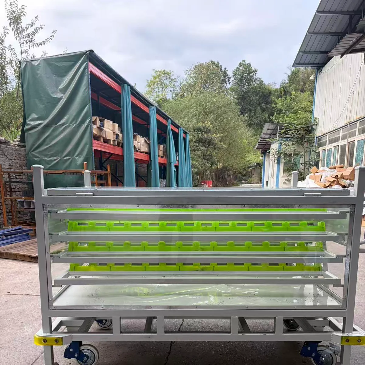
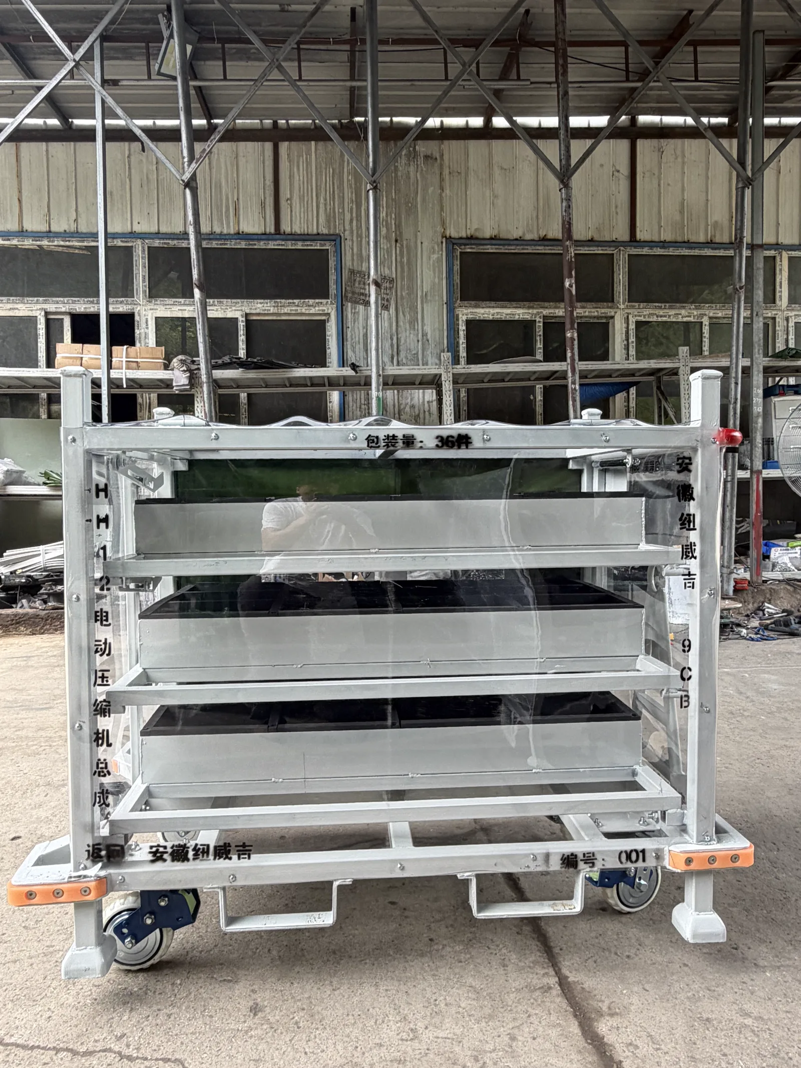
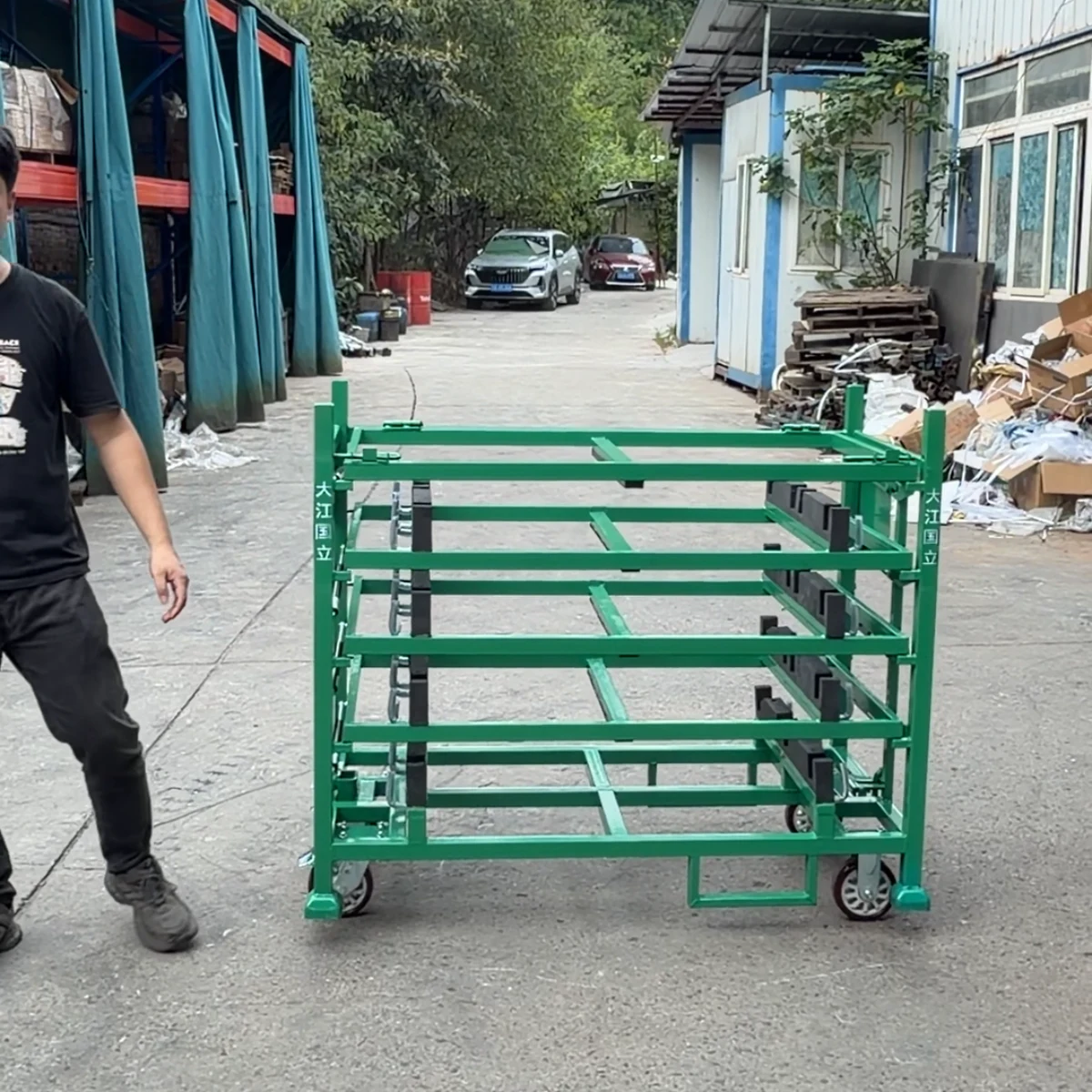
User-supplied real product photograph, square-cropped for the catalog. It shows this configuration but does not establish dimensions, payload, PU performance or customer acceptance.
Multi-Level PU Locator Parts Trolley
A custom mobile automotive parts trolley that combines multi-level access, part-shaped polyurethane locating points and an optional protective enclosure. Tray layout, contact geometry, wheel arrangement and payload are defined from the approved part and plant route.

HAOFU Engineering Team
Reviewed 2026-08-31
Use this configuration when a lightweight or surface-sensitive component needs repeatable positions on a mobile multi-level trolley. Send the part data, permitted contact zones, loading sequence, route and handling rules before the tray and PU locator design is frozen.
At a Glance
- Configuration
- Custom to the approved part, rack and route
- Primary role
- Separated multi-level positioning and mobile part presentation
- Required inputs
- part data, contact zones, quantity per trolley, loading sequence and plant route
- Material / interface
- Confirmed in the approved project drawing and specification
- Validation
- Fit, access, handling and controlled requirements agreed before production release
- Supply scope
- Component-only or integrated rack/trolley scope, as quoted
Real product views
Product Gallery
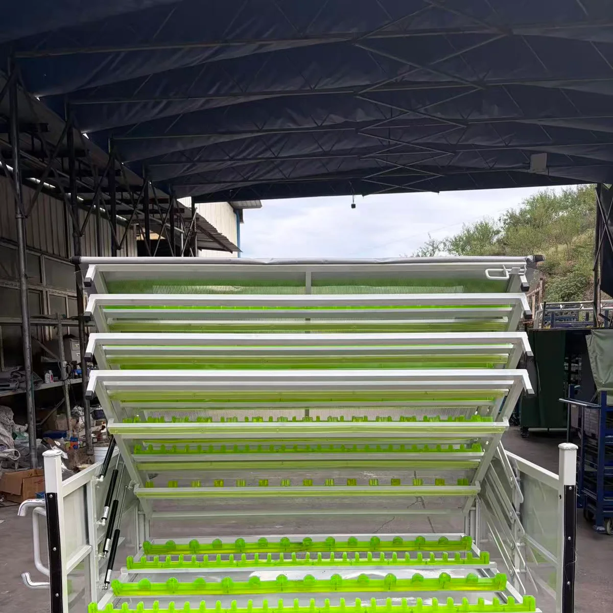
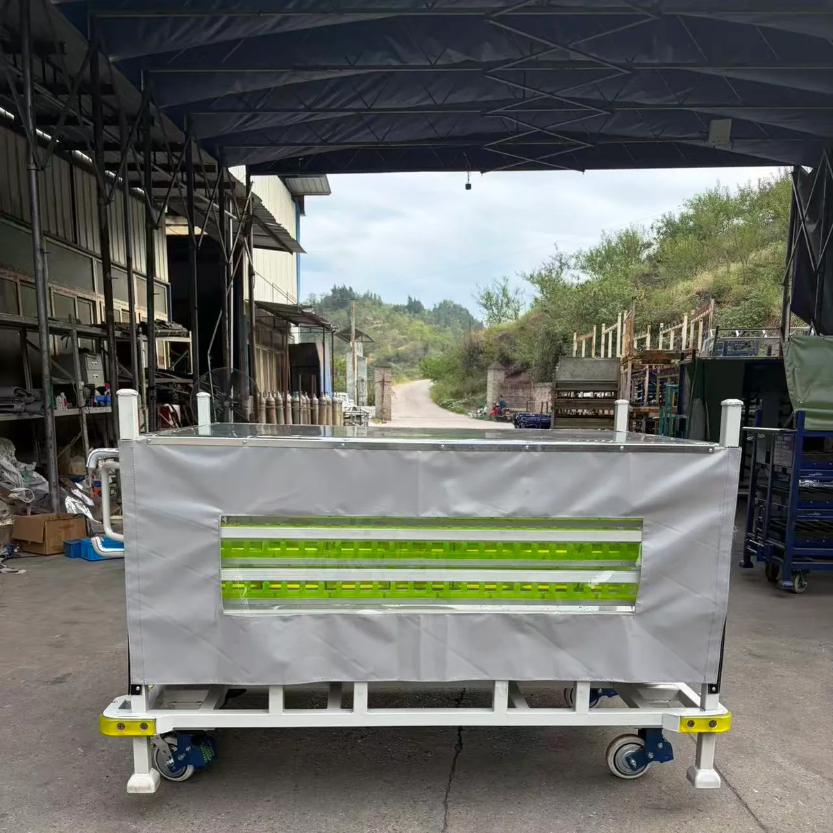
Real user-supplied product views show open and covered states. Final tray count, PU geometry, cover and handling interfaces are engineered for the buyer's approved part and route.
Description
Multi-Level PU Locator Parts Trolley is a project-specific product or rack component used within returnable automotive packaging and in-plant material handling. HAOFU develops it around the approved part, contact restrictions, access, handling route and buyer specification. It is not presented as a universal off-the-shelf performance specification.
This page owns the commercial intent for multi-level PU locator parts trolley. Buyers comparing complete carriers should also review Material Handling Trolleys; the main product page remains the owner for the broader rack or trolley category.
What must be decided before design release
| Input area | Design decision |
|---|---|
| Part and contact data | Define allowed support zones, locator geometry and surface restrictions. |
| Loading sequence | Set tray pitch, opening direction and operator access. |
| Plant route | Select caster arrangement, brakes, tow interface and clearances. |
| Protection scope | Decide whether an open frame, curtain or viewing panel is required. |
Suitable application scope
- Line-side presentation of lightweight automotive components
- Controlled WIP transfer between workstations
- Returnable internal logistics where separated part positions are required
Claim boundary: The photographs do not establish tray count, payload, caster duty, braking performance or suitability for another part. Those values require project review and approval.
RFQ information to send
- Controlled part drawing, 3D data, photo or sample
- Part mass, centre of gravity and quantity per trolley
- Permitted and prohibited contact zones
- Loading side, access sequence and operator constraints
- Route, floor, turning space and handling equipment
HAOFU manufactures in China and ships globally. Start with the custom rack and trolley design process, then send the controlled requirements for review. Final dimensions, material callouts, capacity, interfaces, validation and commercial terms belong in the approved quotation and drawing.
How the requirement moves to approval
- Define: collect controlled part, rack, route and buyer-standard inputs.
- Design: agree contact geometry, interfaces, access and maintainable components.
- Review: check the concept against loading, handling, return and service conditions.
- Validate: approve the sample and recorded acceptance criteria before production release.
Industry terminology references
The following industry pages were used to confirm buyer terminology and specification inputs. Their company-specific claims are not adopted as HAOFU claims.
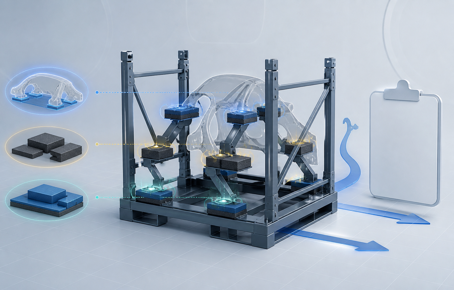
Guides & Resources
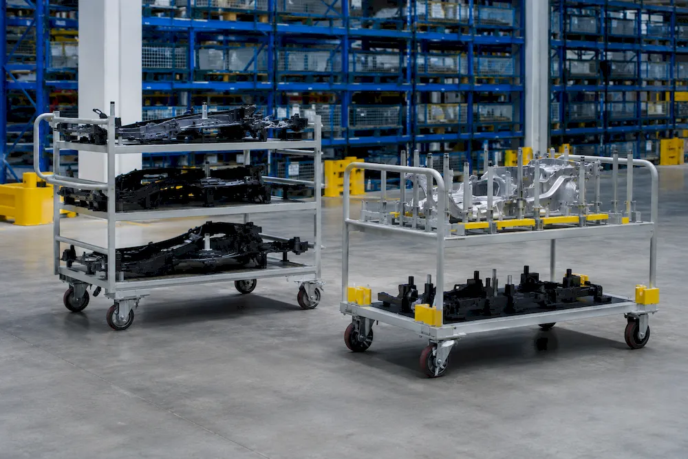
Learn more about choosing and using multi-level pu locator parts trolley.
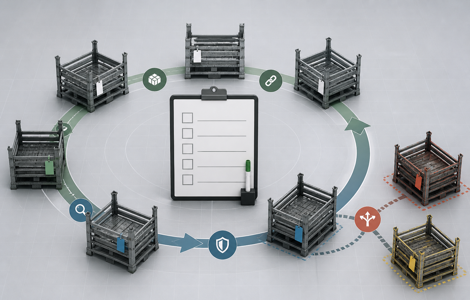
Applications, Engineering & Buyer Tools
Move from product discovery to a controlled requirement, application review and inspection plan.
Multi-Level PU Locator Parts Trolley — Frequently Asked Questions
Is the multi-level PU locator parts trolley a standard catalog item?+
No. It is configured from the controlled component, rack interface, duty and buyer requirements. Reference images show the product family; they do not define the final dimensions, material or performance.
What information is needed to quote multi-level PU locator parts trolley?+
Please provide part data, contact zones, quantity per trolley, loading sequence and plant route, plus target quantity, destination and any controlled buyer standard. HAOFU can then define what is included in the design, sample and quotation scope.
Can it be supplied for an existing rack or trolley?+
Potentially. Send the existing rack drawing, mounting details, photographs and the approved part data. The team will review fit, access, replacement and any effect on the complete carrier before proposing an interface.
What does the reference image prove?+
It shows a configuration or component type only. It does not establish tray count, payload, caster duty or PU performance. Final claims belong to traceable material data, an approved drawing and agreed validation records.
How is the design approved before volume production?+
The controlled inputs are converted into a design and sample scope. The buyer reviews fit, contact, access, handling and any specified test or inspection criteria before production release.
Ready to Improve Your Material Handling?
Tell us your requirements and our engineers will contact you within 24 hours.
Contact Us Now