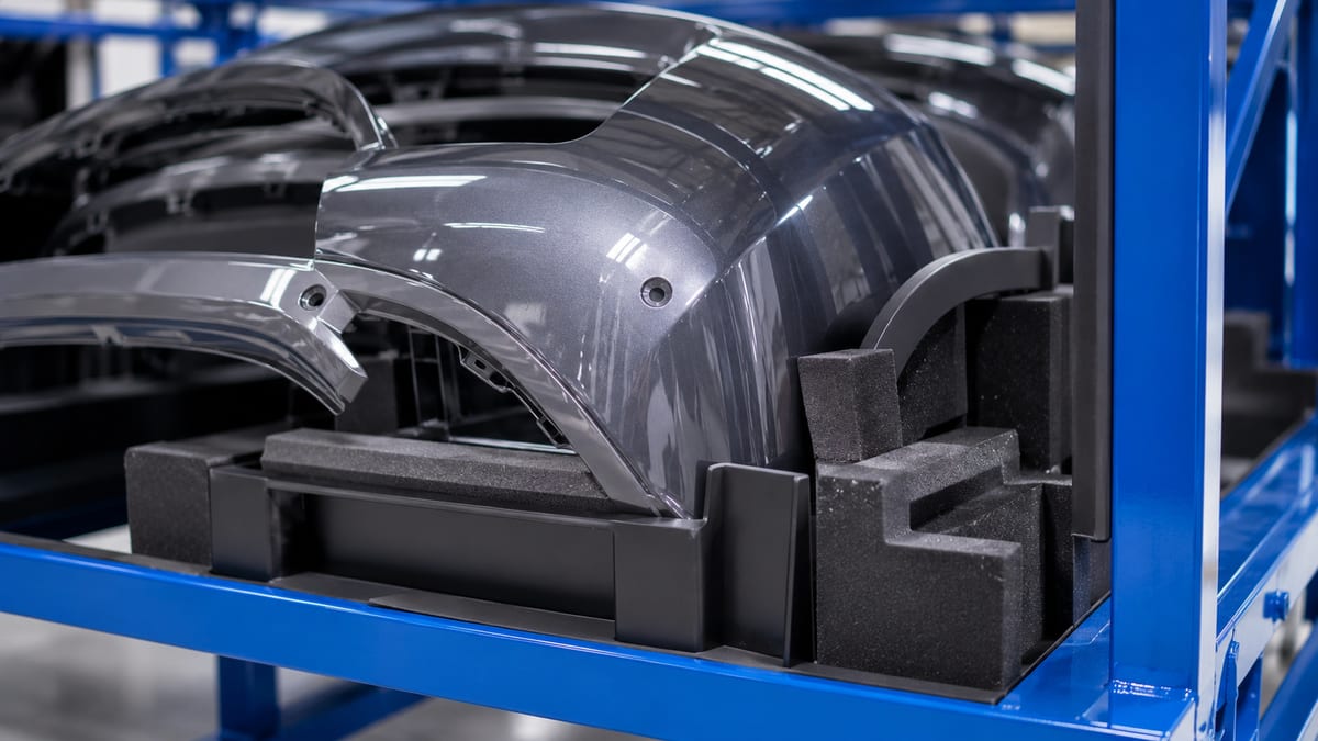
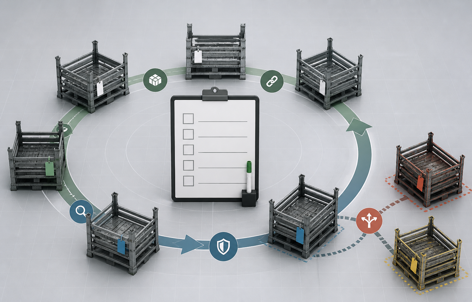
Automotive Rack Dunnage Design and Sample Checks

Design automotive rack dunnage from the actual part geometry, weight, center of gravity, permitted support zones, restricted cosmetic surfaces, loading direction and logistics route. Select foam, rubber, polyurethane, plastic locators, textile pockets or other materials by the required contact and service conditions, then check fit, insertion, removal, movement and replaceability with representative parts before production.
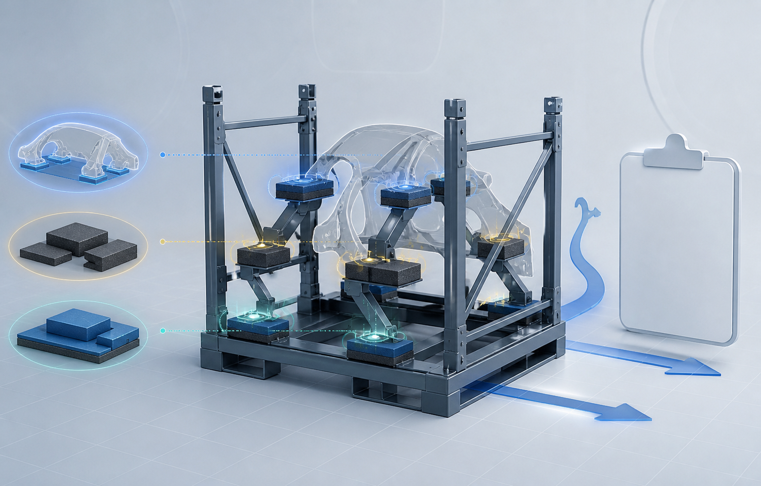
Automotive rack dunnage should be designed from the actual part geometry, weight, center of gravity and surface restrictions. Mark permitted supports and no-contact zones, then add the loading direction, operator or equipment access, quantity per rack and transport route. Those inputs guide the choice of foam, rubber, polyurethane, plastic locators, textile pockets, dividers or restraints.
Start with the part, not the dunnage material
Foam, rubber, plastic blocks, dividers and straps are interfaces between a part and a rack. Begin by marking the part revision, cosmetic or restricted surfaces, permitted supports, quantity per rack, orientation and access needed for loading or removal. Then map loading, storage, transport, unloading and empty return.
The AGC Automotive packaging guidelines illustrate the common industry sequence of design, prototype review and later production purchasing.
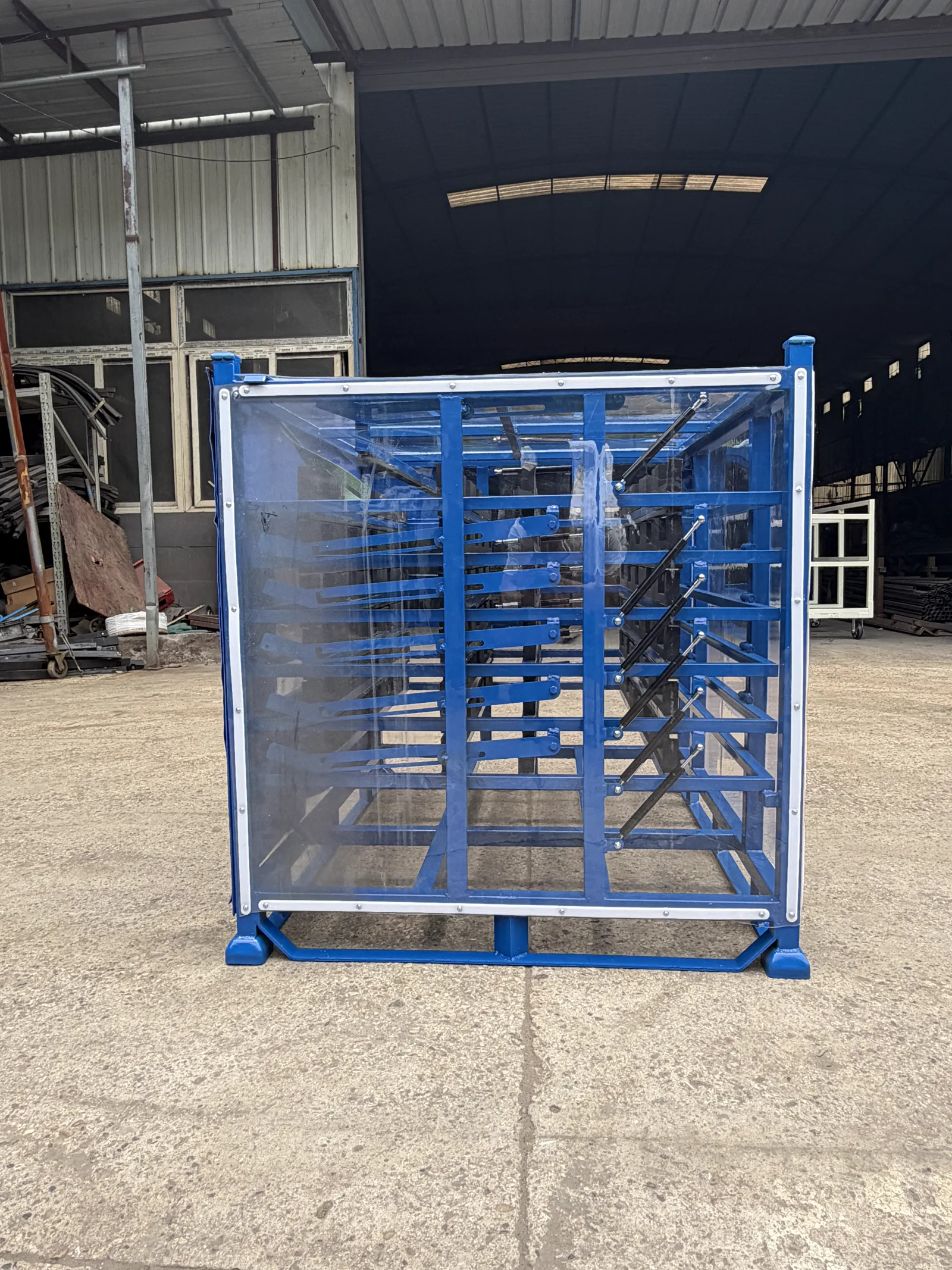
Inputs for a practical dunnage design
| Input | What to identify | Design output |
|---|---|---|
| Part and zones | Revision, orientation, permitted supports and restricted surfaces | Support and clearance map |
| Dunnage interface | Pad, separator, locator or restraint location and replacement approach | Material, geometry and attachment |
| Working route | Loading, handling, storage, transport and return states | Access and movement checks |
| Sample trial | Fit, insertion, removal, part movement and wear points | Drawing updates before production |
Run a four-step dunnage sample check
- Map the part: record part geometry, weight, orientation, quantity and permitted or restricted contact zones.
- Design the interfaces: show where locators, pads, dividers and restraints contact the part and how they attach to the rack.
- Trial representative parts: check insertion, removal, access, movement and the intended handling sequence.
- Update the production drawing: record material, geometry, attachment, replacement method and inspection points.
Keep the sample review separate from a generic safety claim
Powered handling and storage have to reflect the actual workplace condition. OSHA materials-handling guidance is a useful reminder to review the real handling context, while AAR technical-services references show that loading methods and materials can require controlled evaluation. Neither source approves a specific automotive rack, pad or route for this project.
Use adjacent guides for the next decision
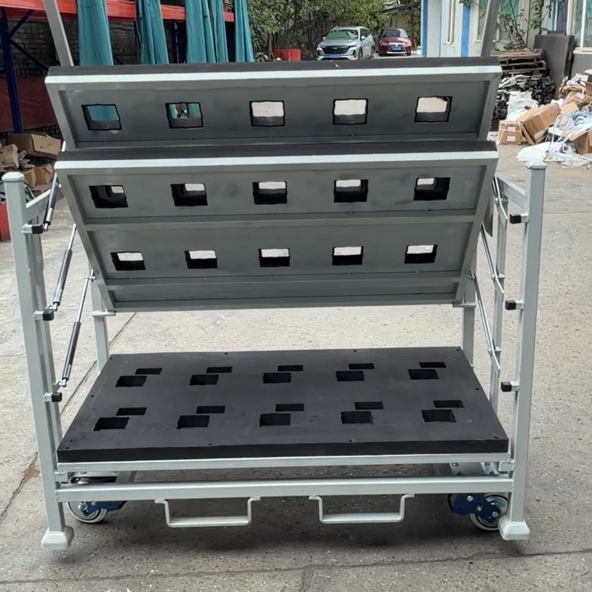
For protection features, see our painted-parts dunnage guide; for the broader product and engineering context, use the automotive metal-racks guide and the automotive rack design guide. A visible configuration context is available in our EVA foam-slot automotive rack video; it is a project video, not an acceptance record for this brief. The paired returnable fleet acceptance checklist starts after an approved design becomes a circulating programme.
Explore custom automotive parts racks, then send the controlled part drawing or sample, contact restrictions, quantity, route, handling equipment and intended approval evidence through customization.
Frequently Asked Questions
- What information is needed to design automotive rack dunnage?
- Provide part geometry, weight, center of gravity, orientation, quantity per rack, permitted support zones, sensitive surfaces, loading direction and logistics route.
- Which materials are used for automotive rack dunnage?
- Options include EVA or other foams, rubber pads, polyurethane or plastic locators, textile pockets, dividers and restraints. Select them from the contact load, surface and environment.
- What should a dunnage sample check include?
- Check part insertion and removal, locator fit, clearances, movement, operator or equipment access, transport orientation and replaceable-component installation.
- How can rack dunnage be made replaceable?
- Use accessible fasteners or modular holders, identify the component, and include replacement dimensions and material in the drawing and spare-parts list.
- What should I send for an automotive dunnage rack quote?
- Send the part drawing or sample, weight, contact restrictions, quantity, orientation, handling equipment, route, preferred materials and project quantity.