Multi-Level Foam Dunnage Trolley
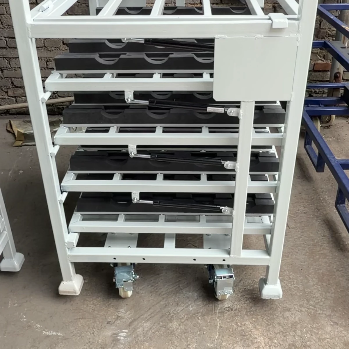
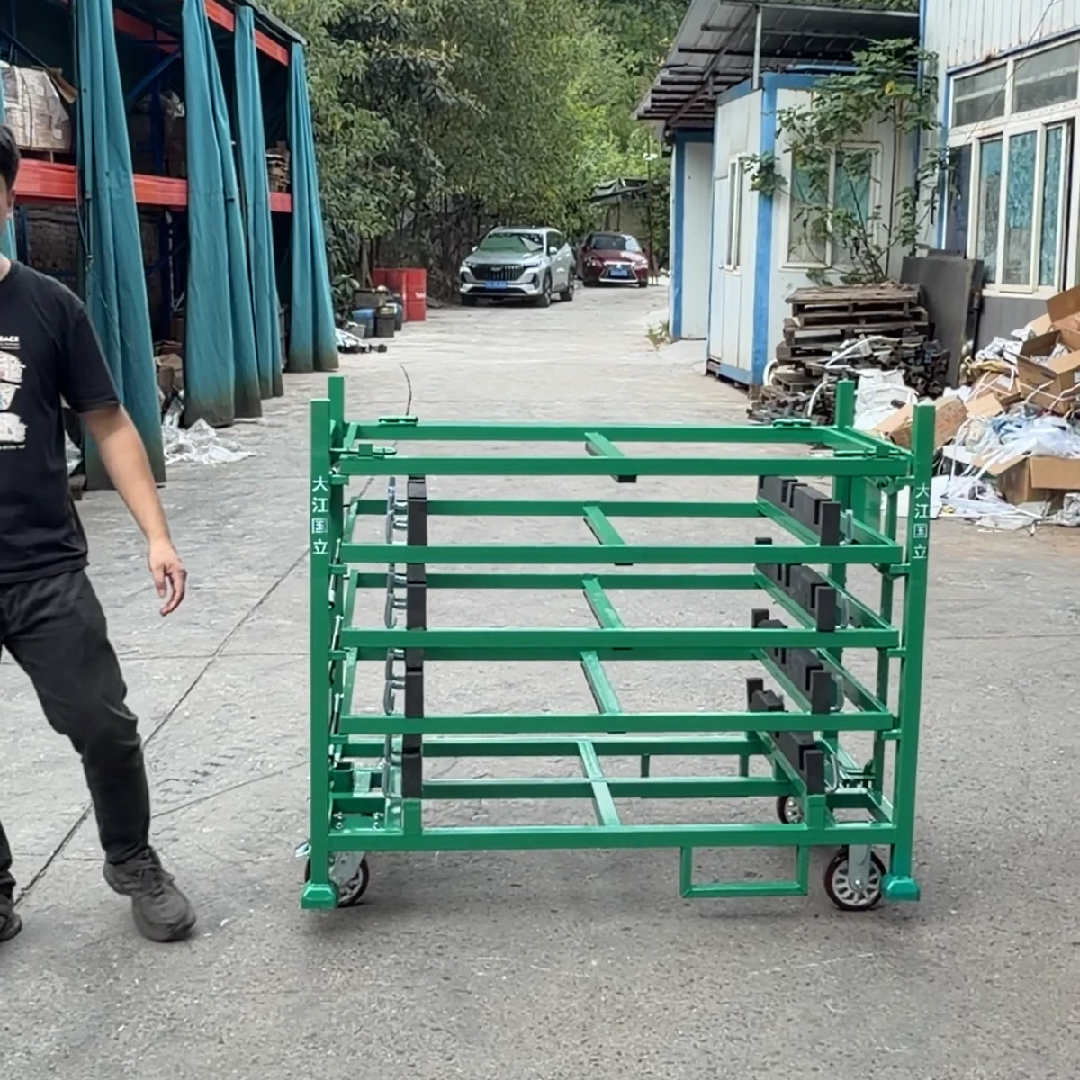
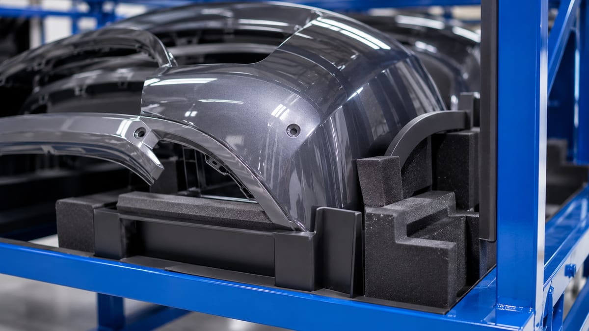
A custom multi-level foam dunnage trolley with separated rows of shaped, non-metal contact points for controlled part presentation. Level count, foam profile and trolley interfaces are project-specific.
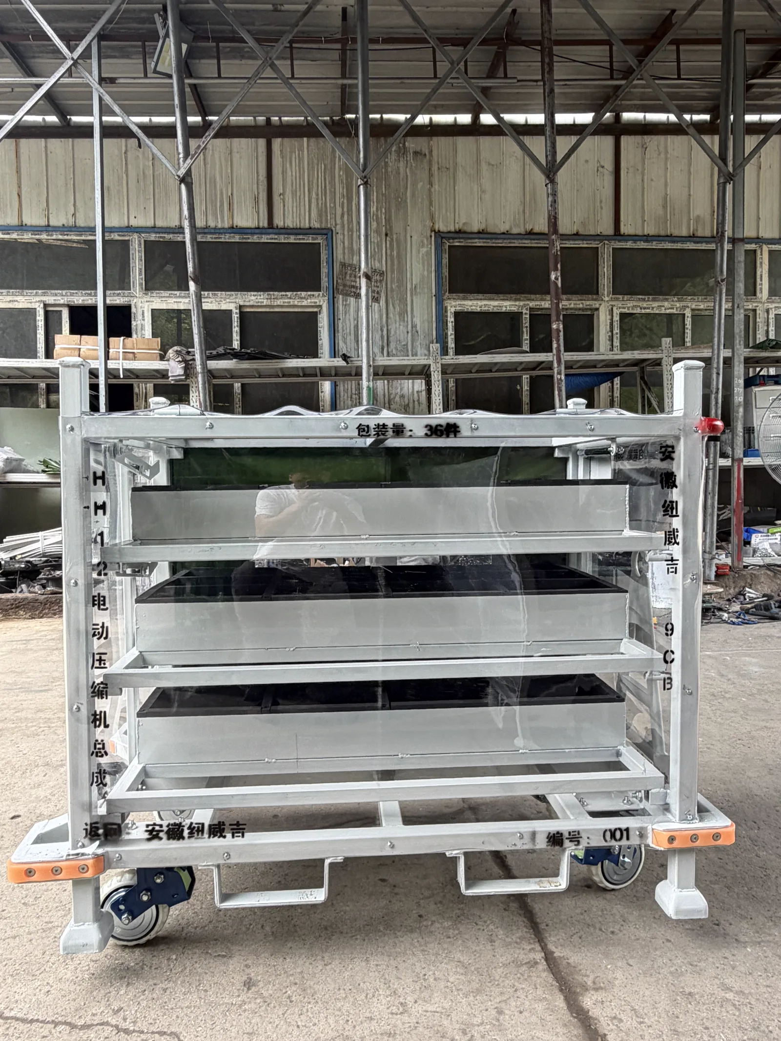
A multi-level foam dunnage trolley is a reusable steel logistics carrier configured from the actual part, its protected contact points, loading sequence and handling route. This photographed example shows multi-level shaped foam dunnage and wheeled steel frame; send the part data, route, carrier quantity and destination for a custom manufacturer quotation.
At a Glance
- Structure
- Custom welded steel returnable rack or trolley
- Visible example
- shaped foam contact points on multiple levels
- Part protection
- Dunnage, dividers and non-metal contact materials as specified
- Handling
- Casters, forklift or tow interface selected for the agreed route
- Capacity
- Confirmed from the approved part, quantity and handling conditions
- Identification
- Project label, asset ID or traceability method as specified
Built example
Product Gallery
Real photos of a custom-built configuration. Dimensions, part count and handling details are specified for each buyer's programme.


Description
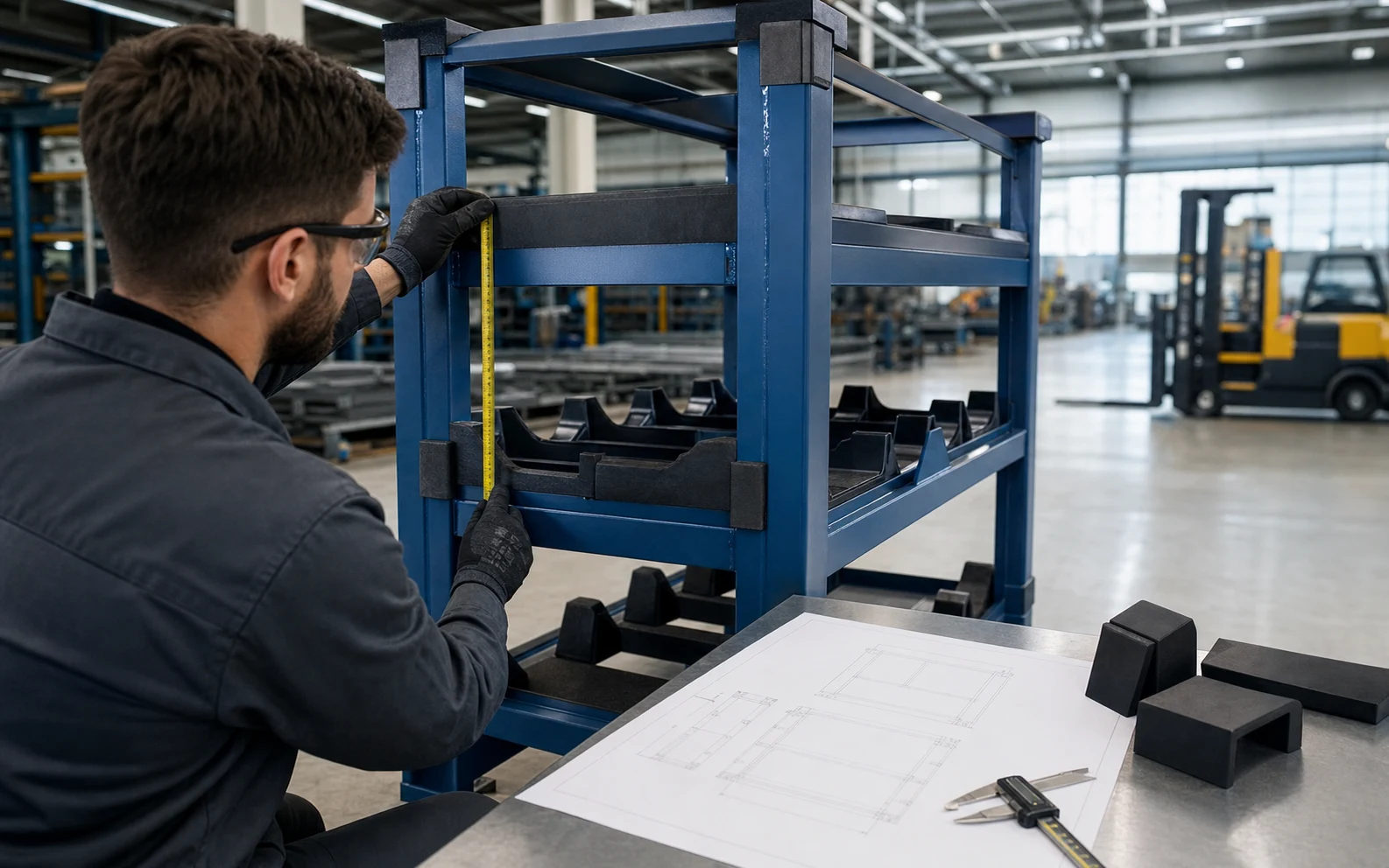
A multi-level foam dunnage trolley is a purpose-built returnable carrier, not a catalogue-size rack. This real photographed configuration uses multi-level shaped foam dunnage and wheeled steel frame. For purchasing and packaging engineers, the correct design starts with the part drawing, weight, contact surfaces, quantity per carrier and handling route.
What this configuration is designed to solve
It keeps part positions, loading access and protection aligned through storage, line-side movement and the return loop. Use the photographed frame, dunnage and access mechanism to discuss the arrangement you need, then set dimensions, part count and handling details from your own drawing and route.
Specification inputs for a custom multi-level foam dunnage trolley
| Buyer input | Design decision |
|---|---|
| Part drawing, sample and sensitive contact areas | Dunnage profile, clearance and retention |
| Parts per carrier and loading sequence | Level count, access side and presentation |
| Manual, tugger or forklift route | Casters, base, tow or lift interface |
| Storage and empty-return condition | Cover, folding, stacking or nesting concept |
| Destination and inspection requirements | Finish, identification and acceptance plan |
Decisions to settle before requesting a quote
- Choose the stable part orientation and mark the surfaces that may contact the dunnage.
- Check the loading motion and clearance at every tray instead of copying another component's layout.
- List each caster, tugger or forklift move so the base works across the complete route.
- State how the carrier is identified, returned and inspected during repeat use.
Start with a usable RFQ
Send the drawing or sample, part weight, target quantity per carrier, loading direction, handling route, destination and expected order quantity. HAOFU can turn this into a customisation brief and sample-review path. Read the related buyer guide, the protection and handling guide, the rack RFQ checklist.
Useful planning references: OSHA materials-handling guidance covers powered-truck loading and transfer considerations. GS1 GRAI explains a standard identifier for reusable transport assets when the buyer's tracking system needs one.
Configuration comparison
Choose the multi-level foam dunnage trolley interface before material or size
The useful choice is driven by how the component meets the part, rack and operating route. Compare the interface and service task before fixing a material callout.
| Configuration | Use it when | Main trade-off | Send with the RFQ |
|---|---|---|---|
| Dedicated fixed interface | One controlled part or rack revision uses the same contact and mounting position. | Direct positioning with a part-specific geometry; revisions may require a changed component. | Part CAD, rack interface, permitted contact zones, tolerances and attachment details. |
| Replaceable modular interface | Contact pieces need planned inspection or replacement without rebuilding the carrier. | Serviceable wear component; fastener access, indexing and spare identification need space. | Replacement direction, tool clearance, fastener standard, identification and spare quantity. |
| Shared interface for variants | A defined part family can use common datums without unstable contact or interference. | Fewer unique components; the full variant envelope and changeover method must be checked. | Variant matrix, common datums, worst-case envelope and changeover sequence. |
From requirement to quotation
Prepare a multi-level foam dunnage trolley RFQ
Connect the component to the controlled part, carrier and maintenance task so suppliers price the same requirement.
- 1
Control the mating geometry
Send the current part and rack data with revisions and the exact interface location.
Output: Approved geometry baseline
- 2
Mark contact and motion
Show allowed contact, keep-out areas, load or movement direction and required clearances.
Output: Interface and motion map
- 3
Define material and environment
State buyer material specifications, temperature, cleaning, exposure and identification needs that actually apply.
Output: Material requirement
- 4
Plan installation and service
Add mounting access, replacement method, quantity, destination and sample-review expectations.
Output: Quotation-ready component brief
Original project video
See the photographed configuration in motion
This embedded video is supplied with this product's real photo set. It documents the configuration only; final specifications remain project-specific.
Guides & Resources
Learn more about choosing and using multi-level foam dunnage trolley.
Applications, Engineering & Buyer Tools
Move from product discovery to a project specification, application check and inspection plan.
Multi-Level Foam Dunnage Trolley — Frequently Asked Questions
Is this multi-level foam dunnage trolley an off-the-shelf product?+
No. The images show a real custom-built configuration with shaped foam contact points on multiple levels. HAOFU confirms the final frame, part positions, access and handling details from your component and logistics flow.
What information is needed to quote the rack or trolley?+
Please provide a part drawing, 3D data, photo or sample; part weight; quantity per carrier; sensitive contact areas; loading direction; handling route; destination; and target quantity. Those inputs make the quotation and engineering scope usable.
Can the dunnage be changed for our component?+
Yes. Locators, foam, rubber, plastic blocks, dividers and retention features are selected around the approved component's contact points and clearance needs. They are not copied from an unrelated rack.
Can it be moved by casters, forklift or tugger?+
The handling interface is selected from the real route and equipment. A project may use casters, forklift entry, a tow connection or another agreed interface; clearances, load conditions and operating rules need review before approval.
How should a returnable rack be identified?+
The buyer can specify a project label, barcode, RFID or other asset-identification approach. GS1 describes GRAI as an identifier suitable for reusable transport assets when a shared tracking system requires it; the actual identifier owner and data process are agreed by the supply-chain parties.
Discuss your part or handling task
Send a photo, drawing or short description to start your enquiry.
Contact Us Now