Automotive Brake Booster Returnable Rack
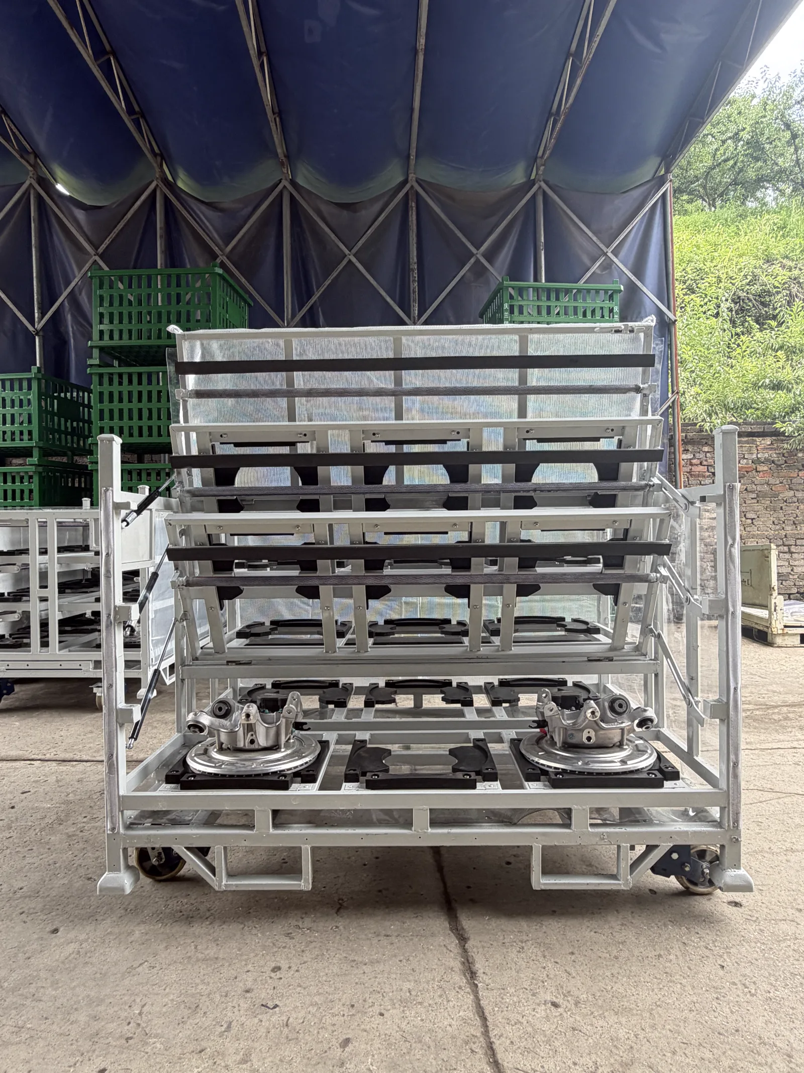
A custom automotive brake booster returnable rack that holds brake booster assemblies in defined, protected positions. The multi-level steel frame integrates part-specific dunnage, fold-down access, forklift pockets and caster options for repeatable transport and line-side supply.
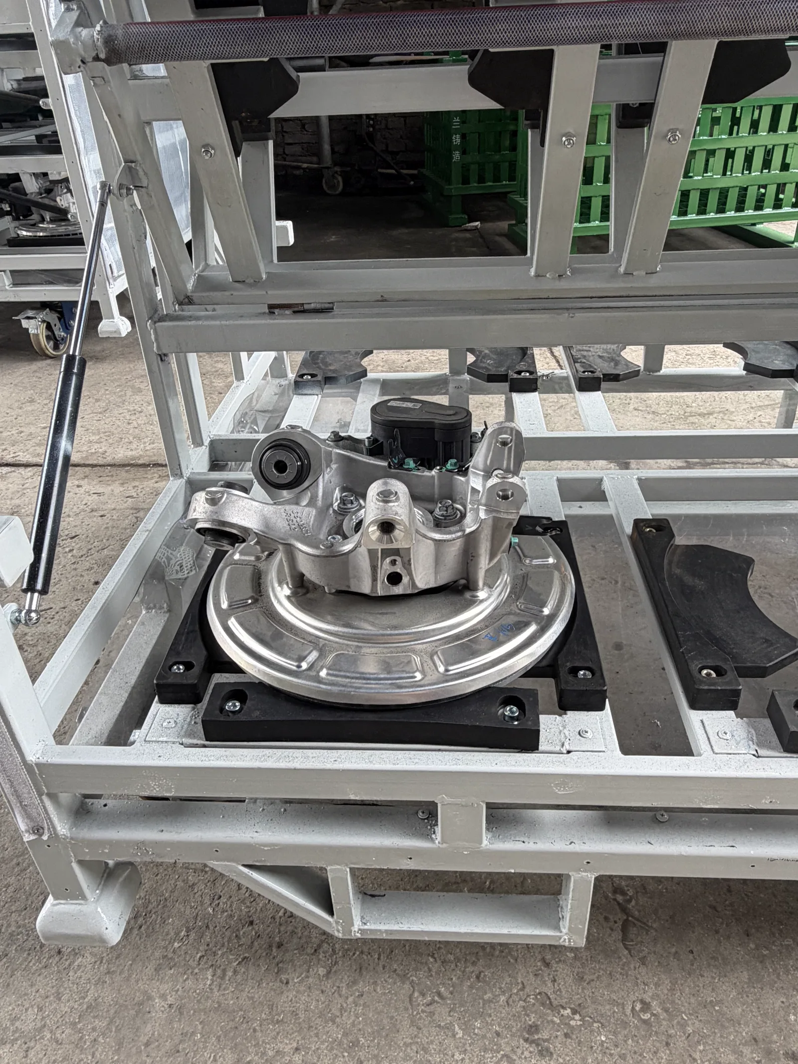
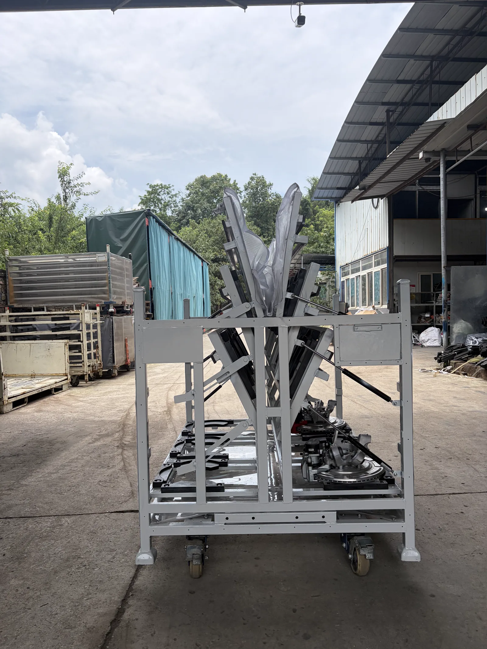
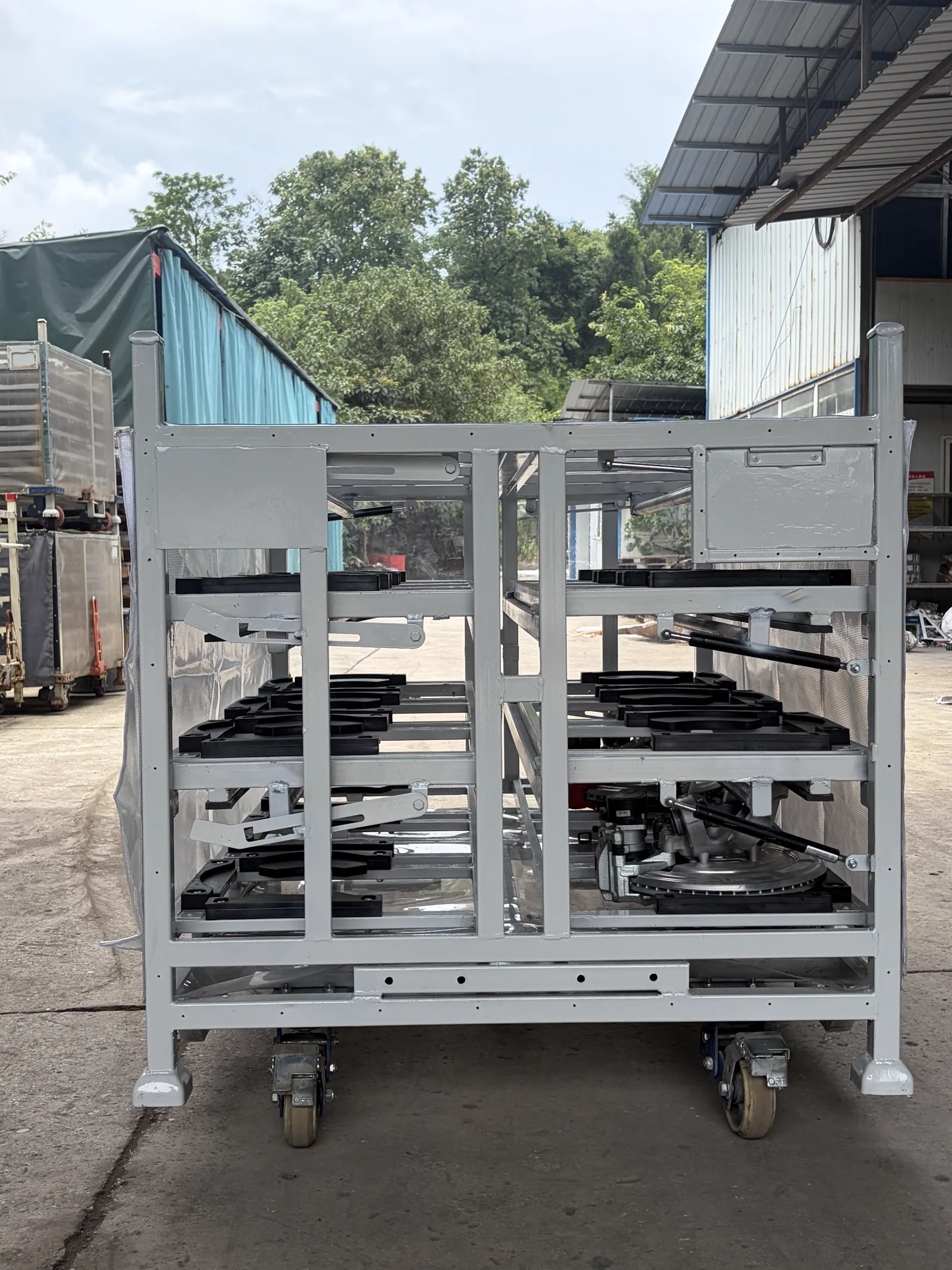
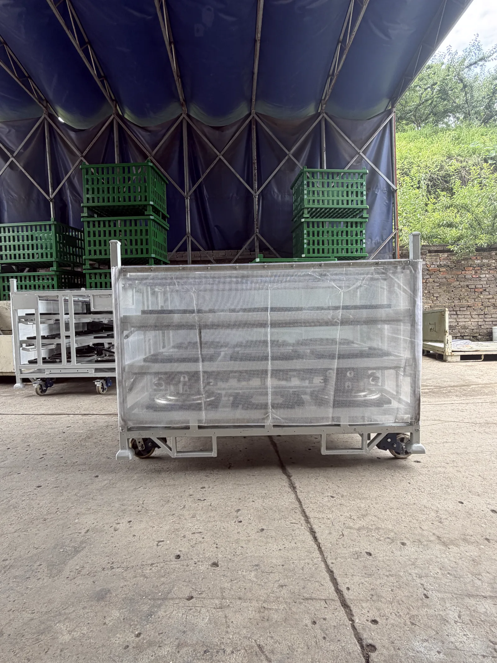
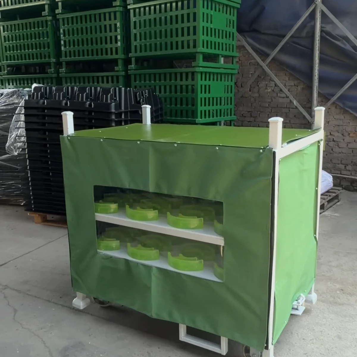
This photographed brake booster returnable rack uses dedicated lower nests and opening multi-level frames to separate assemblies while preserving loading access. The useful RFQ starts with the current part CAD, stable support features, sensitive ports and studs, loading direction, pieces per rack and every caster, fork or tow movement.
At a Glance
- Structure
- Custom welded steel multi-level returnable rack
- Part retention
- Dedicated dunnage pockets and protected contact points
- Access
- Fold-down or opening sections configured for the loading process
- Handling
- Forklift pockets, stack features, casters or tow interface as required
- Capacity
- Specified to brake booster geometry, weight and quantity per rack
- MOQ
- Typically 20–50 units; trial orders available
- Lead time
- Historical planning reference: sample about 7–15 days; production about 25–45 days. Reconfirm for each quotation.
Built example
Product Gallery
Real photos of a custom-built configuration. Dimensions, part count and handling details are specified for each buyer's programme.
Description
An automotive brake booster returnable rack is a multi-level steel transport rack that locates each brake booster assembly on dedicated dunnage rather than letting heavy, irregular components touch or shift against one another. The illustrated rack combines a rigid returnable frame with protected contact points, opening access and forklift-ready base details for controlled movement through an automotive supply chain.
Brake-system assemblies vary in geometry, connection layout and surface sensitivity, so this is not an off-the-shelf load rating or universal tray pattern. HAOFU designs the locator position, protective material, orientation, parts per rack and handling interfaces around the approved part and programme requirements.
Buyer-focused design features
- Dedicated dunnage pockets to locate each assembly and separate contact points
- Multi-level layout to increase density while retaining operator access
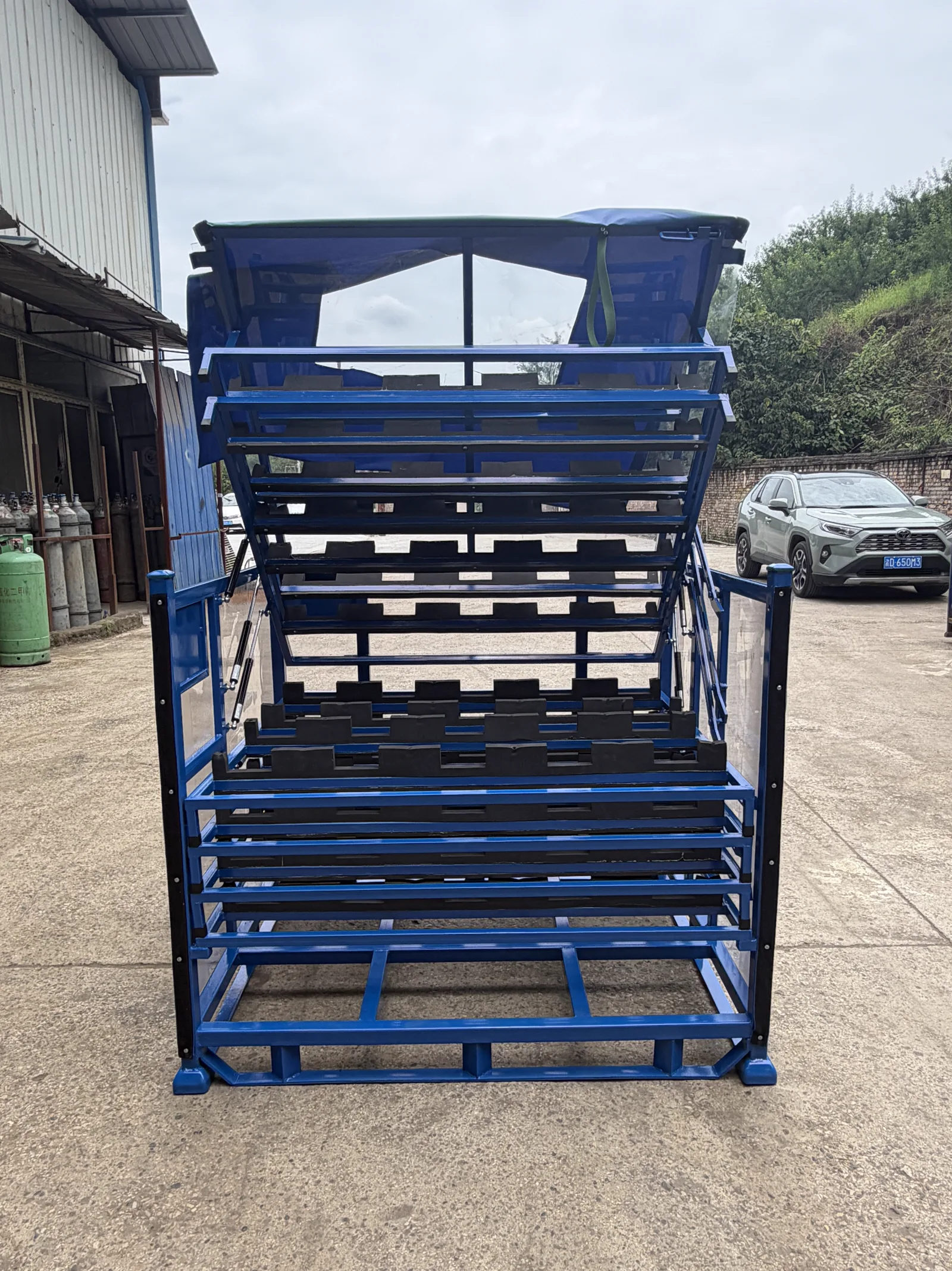
- Fold-down or opening sections for loading and unloading as required by the process
- Forklift pockets, stacking structure, casters or tow interfaces selected for the route
- Protective screens or covers available for transit and storage conditions
Information needed for a quotation
| Please provide | Why it matters |
|---|---|
| Part drawing, 3D data or representative sample | Defines the locating, clearance and protection strategy |
| Part weight and required quantity per rack | Sets the frame, tray and stacking design inputs |
| Loading direction and operator access | Determines access panels, fold-down arms and presentation height |
| Forklift, tugger or manual handling route | Determines the base, wheels, tow point and aisle allowances |
| Return loop and destination | Guides stackability, empty-return efficiency, finish and export packing |
From part data to an approved returnable rack
Our process starts with your part data and handling route, then moves through concept review, sample build and fit validation before volume production. Read how returnable packaging racks reduce damage and waste, review part-protection material options, or send the brake booster drawing for a quotation.
Configuration comparison
Choose the brake booster support and access format
Brake booster geometry can make a high-density layout difficult to load. Compare position control and operator access before selecting how many assemblies fit on each level.
| Configuration | Use it when | Main trade-off | Send with the RFQ |
|---|---|---|---|
| Dedicated machined or moulded nests | One booster design needs repeatable seating from stable housing or flange features. | Clear orientation and separation; new part revisions may require replacement locator pieces. | CAD revision, datum/support faces, keep-out zones, part mass and seating orientation. |
| Common frame with variant locators | A defined part family shares reliable datums but needs different locator details. | Can reduce the number of rack frames while requiring a controlled changeover and variant check. | Variant matrix, shared datums, locator change method and identification requirement. |
| Opening multi-level rack | Upper frames need to move to expose the loading position below. | Supports density and access; tray motion, hold-open state and closing clearance become part of the operating sequence. | Loaded level mass, access envelope, opening motion, operator side and loading order. |
From requirement to quotation
Move from brake booster CAD to a rack quotation
A useful request shows where the assembly may be held, how it is loaded and how the completed rack moves.
- 1
Identify stable features
Mark permitted support faces, sensitive ports and studs, surface restrictions and orientation datums.
Output: Approved contact strategy
- 2
Define access
Show operator or fixture approach, loading direction and the clearance needed above each position.
Output: Level and opening concept
- 3
Define the logistics route
Provide forks, casters or tow moves, storage state, turns and any loaded stacking request.
Output: Frame and base brief
- 4
Complete the RFQ
State parts per rack, total rack quantity, destination, drawing revision and sample review plan.
Output: Custom returnable rack quote
Guides & Resources
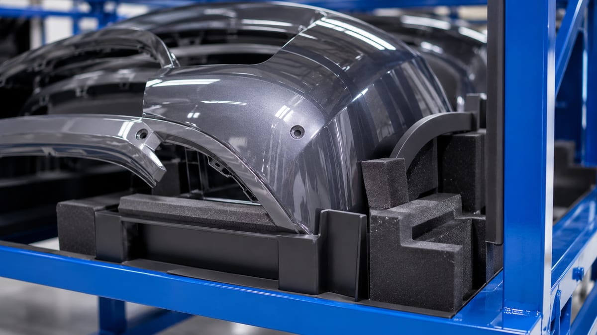
Learn more about choosing and using automotive brake booster returnable rack.
Applications, Engineering & Buyer Tools
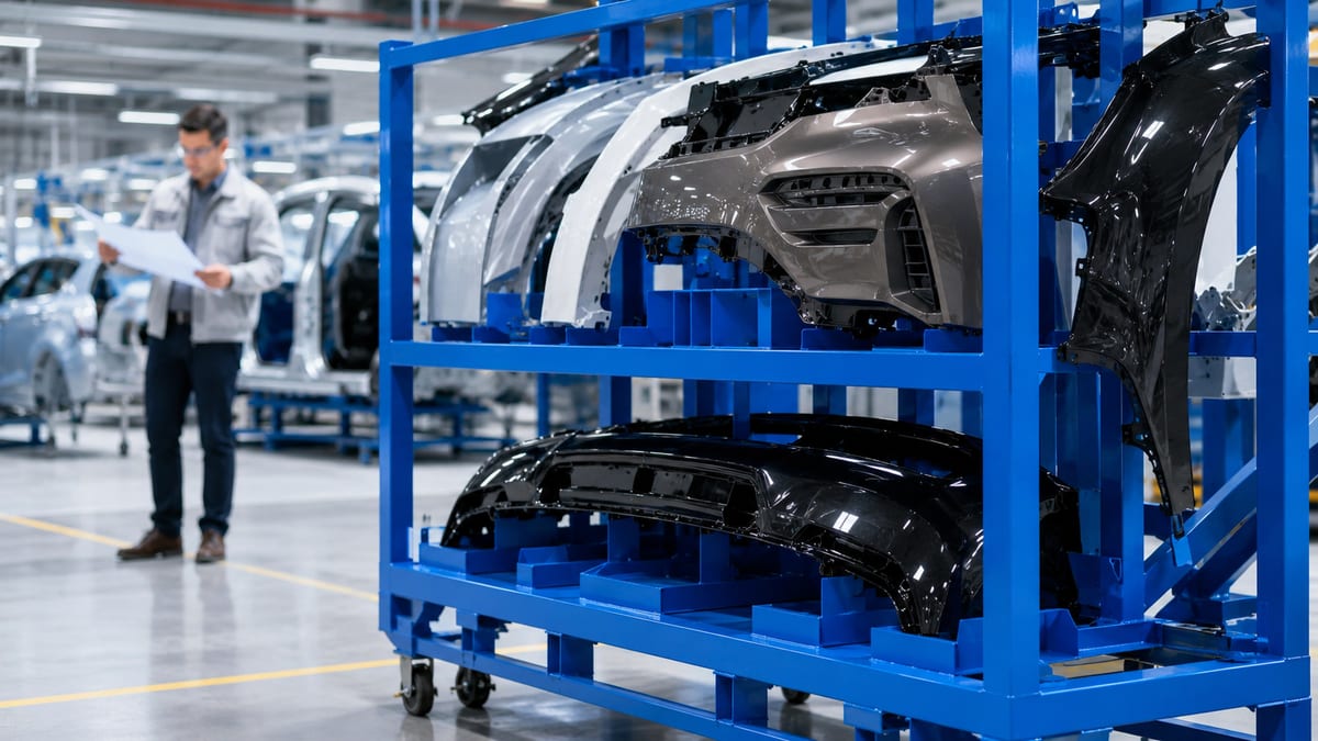
Move from product discovery to a project specification, application check and inspection plan.
Automotive Brake Booster Returnable Rack — Frequently Asked Questions
Can the rack hold different brake booster variants?+
A rack can be engineered for one approved variant or a defined family of variants when the locating geometry and protection requirements allow it. Send the drawings and variant list so the design team can assess the common fixture strategy.
What dunnage is used for brake booster assemblies?+
The dunnage is chosen from the component's contact points and surface sensitivity. Options include plastic locators, rubber pads, EVA and shaped supports that keep assemblies separated and controlled during handling and transport.
Can the rack be moved on casters and by forklift?+
Yes. The base can be designed for caster movement, forklift transfer or both. The selected handling interface depends on load, route, aisle space and how the rack enters the production line.
Can the rack be made stackable or return-efficient?+
Yes. We assess stacking feet, frame stability, fold-down sections and empty-return needs during design. The safe loaded stack height and any folding mechanism are confirmed for the final project configuration.
How do we begin a brake booster rack project?+
Send the part drawing or sample, component weight, quantity per rack, loading direction, logistics route and target quantity. We review the inputs, prepare a concept and validate the design with a sample before production.
Discuss your part or handling task
Send a photo, drawing or short description to start your enquiry.
Contact Us Now