
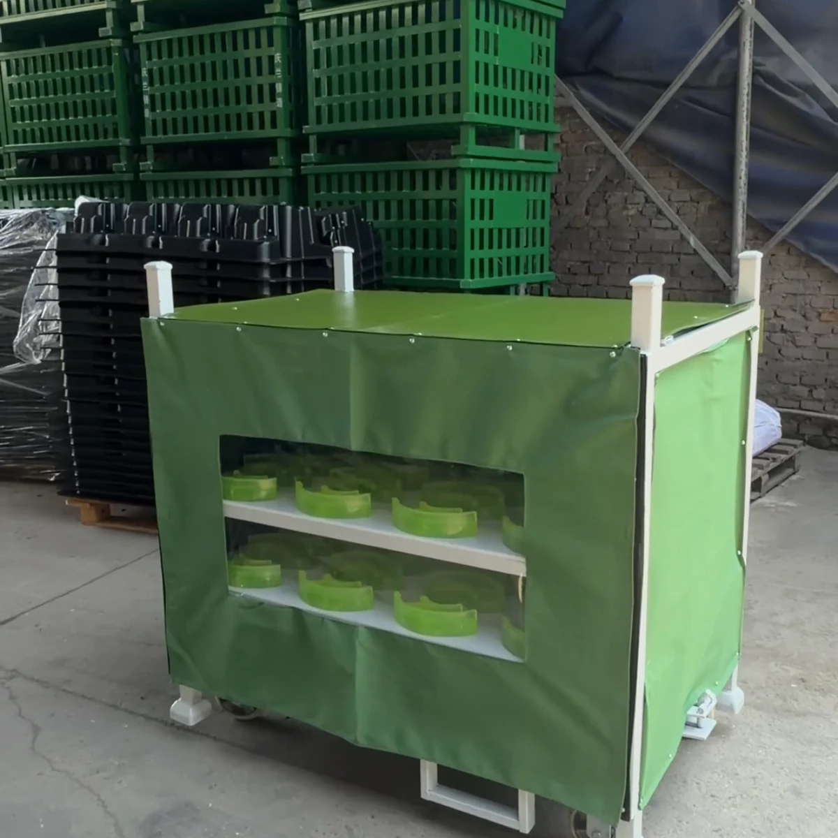
Covered Fold-Down Tray Parts Rack
A custom covered fold-down tray parts rack with protected multi-level positions, a fabric enclosure and a reusable steel base. It is configured around the part, loading access and return route rather than sold as a fixed-size rack.
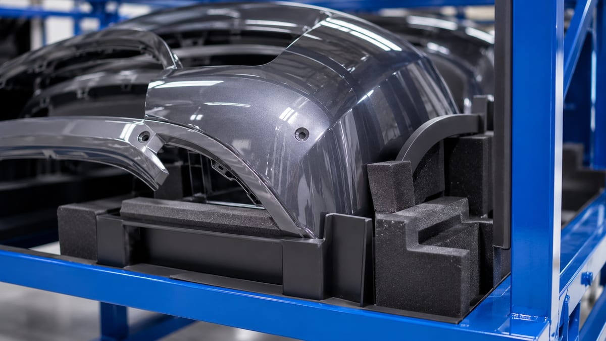
A covered fold-down tray parts rack is a reusable steel logistics carrier configured from the actual part, its protected contact points, loading sequence and handling route. This photographed example shows fabric cover and shelf-mounted locating positions; send the part data, route, carrier quantity and destination for a custom manufacturer quotation.
At a Glance
- Built example
- Covered steel rack with multi-level opening tray positions
- Tray arrangement
- Set from part height, loading motion and required access to lower levels
- Part contact
- Locator and non-metal contact details follow the approved component
- Cover
- Fabric enclosure and opening positioned around the selected loading side
- Handling
- Fork, caster or other base interfaces selected for the actual route
- Quote basis
- Part CAD, mass, pieces per rack, tray motion, route, quantity and destination
Built example
Product Gallery
Real photos of a custom-built configuration. Dimensions, part count and handling details are specified for each buyer's programme.


Description
A covered fold-down tray parts rack is a purpose-built returnable carrier, not a catalogue-size rack. This real photographed configuration uses fabric cover and shelf-mounted locating positions. For purchasing and packaging engineers, the correct design starts with the part drawing, weight, contact surfaces, quantity per carrier and handling route.
What this configuration is designed to solve
It keeps part positions, loading access and protection aligned through storage, line-side movement and the return loop. Use the photographed frame, dunnage and access mechanism to discuss the arrangement you need, then set dimensions, part count and handling details from your own drawing and route.
Specification inputs for a custom covered fold-down tray parts rack
| Buyer input | Design decision |
|---|---|
| Part drawing, sample and sensitive contact areas | Dunnage profile, clearance and retention |
| Parts per carrier and loading sequence | Level count, access side and presentation |
| Manual, tugger or forklift route | Casters, base, tow or lift interface |
| Storage and empty-return condition | Cover, folding, stacking or nesting concept |
| Destination and inspection requirements | Finish, identification and acceptance plan |
Decisions to settle before requesting a quote
- Choose the stable part orientation and mark the surfaces that may contact the dunnage.
- Check the loading motion and clearance at every tray instead of copying another component's layout.
- List each caster, tugger or forklift move so the base works across the complete route.
- State how the carrier is identified, returned and inspected during repeat use.
Start with a usable RFQ
Send the drawing or sample, part weight, target quantity per carrier, loading direction, handling route, destination and expected order quantity. HAOFU can turn this into a customisation brief and sample-review path. Read the related buyer guide, the protection and handling guide, the rack RFQ checklist.
Useful planning references: OSHA materials-handling guidance covers powered-truck loading and transfer considerations. GS1 GRAI explains a standard identifier for reusable transport assets when the buyer's tracking system needs one.
Configuration comparison
Which tray-access arrangement should the rack use?
Start with the motion required to load the lowest part position. Tray count is only useful when every position can be reached and closed in the intended sequence.
| Configuration | Use it when | Main trade-off | Send with the RFQ |
|---|---|---|---|
| Fixed shelf positions | The part enters horizontally with enough clearance at every level. | Simple structure, but greater vertical pitch may be needed for hands, fixtures and connectors. | Part height, entry angle, loading tool envelope, level pitch and quantity per shelf. |
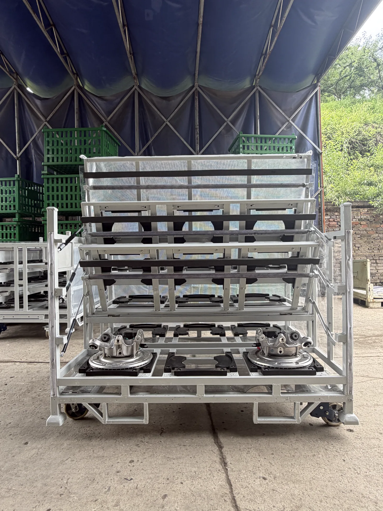
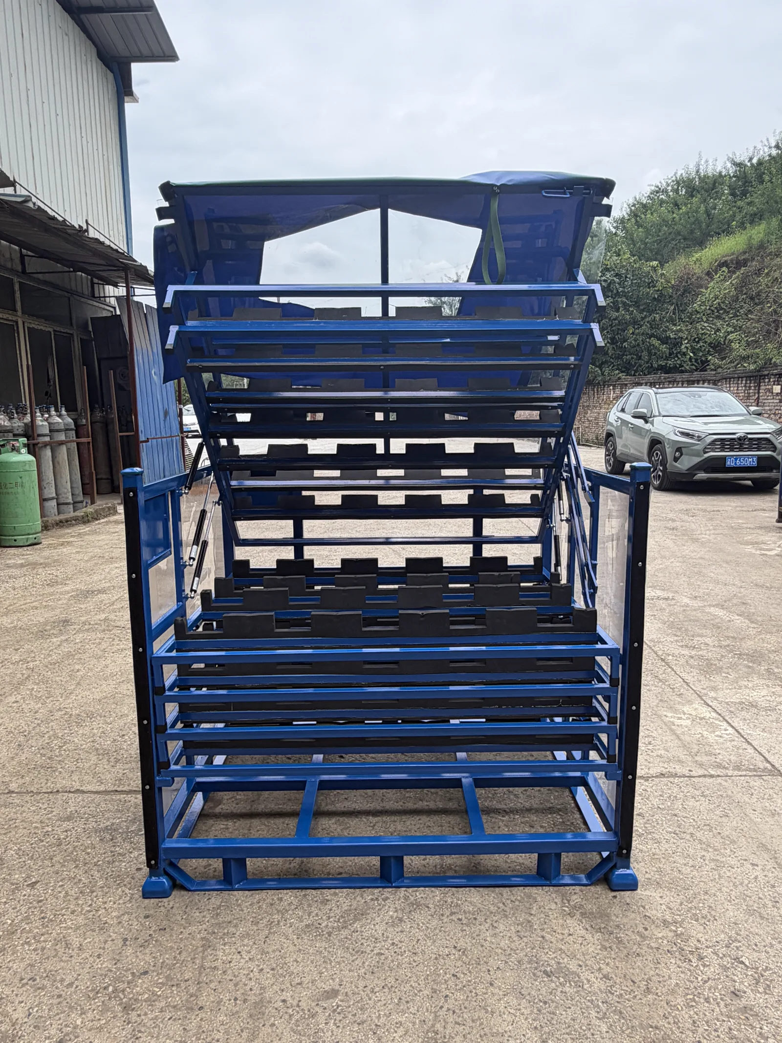
| Fold-down front or tray | Opening the front creates the clearance needed to load or unload lower levels. | Improves access while adding hinges, stops and a defined open/close sequence. | Moving mass, swing envelope, open-state support, operator side and loaded clearances. |
| Assisted opening tray | The defined tray and part mass justify controlled opening assistance. | Can support repeated access; the assistance device must match pivot geometry and real operating load. | Tray mass, part count, centre of gravity, opening angle and cycle sequence. |
From requirement to quotation
Turn the loading motion into a fold-down rack brief
The tray mechanism, part supports and cover need to follow one agreed loading sequence.
- 1
Record the part position
Send CAD, mass, permitted supports, no-contact areas and required orientation.
Output: Locator and clearance map
- 2
Show the load motion
Define the operator or fixture path and which tray opens before each part is moved.
Output: Tray operating sequence
- 3
Add cover and route
Specify the cover opening, visibility, floor movement, forklift entry and storage condition.
Output: Rack and handling concept
- 4
Request the quotation
State pieces per rack, rack quantity, destination, drawing revision and sample checks.
Output: Custom fold-down rack proposal
Original project video
See the photographed configuration in motion
This embedded video is supplied with this product's real photo set. It documents the configuration only; final specifications remain project-specific.
Guides & Resources
Learn more about choosing and using covered fold-down tray parts rack.
Applications, Engineering & Buyer Tools
Move from product discovery to a project specification, application check and inspection plan.
Covered Fold-Down Tray Parts Rack — Frequently Asked Questions
When is a fold-down tray better than a fixed shelf?+
Choose a fold-down or opening tray when a fixed upper level would block the part's loading path or the operator's access to the level below. Send the part envelope and loading motion so the opening arc and tray pitch can be drawn around the real task.
What determines the tray opening angle?+
The required clearance, tray geometry, hinge position, loaded moving mass and the operator or fixture path determine the useful opening angle. Include the open and closed states in the concept review.
Can the cover stay on while parts are loaded?+
The cover can use a front, side or other agreed opening when that arrangement leaves the loading face clear. State whether the cover is for dust, incidental contact or another route condition so access and fastening can be positioned accordingly.
Can each level carry a different part variant?+
Potentially, when the variant geometry, stable supports and loading sequence can share the frame without ambiguous positions. Send the variant drawings and a position matrix for a layout review.
What should I send for a covered fold-down rack quote?+
Send part CAD or a representative sample, mass, allowed contact zones, parts per tray, loading side, opening motion, handling route, cover requirement, rack quantity and destination.
Discuss your part or handling task
Send a photo, drawing or short description to start your enquiry.
Contact Us Now