
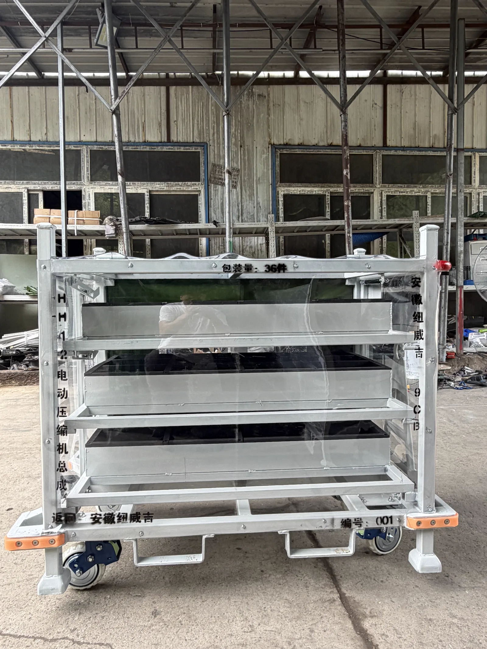
Electric Compressor Assembly Logistics Trolley
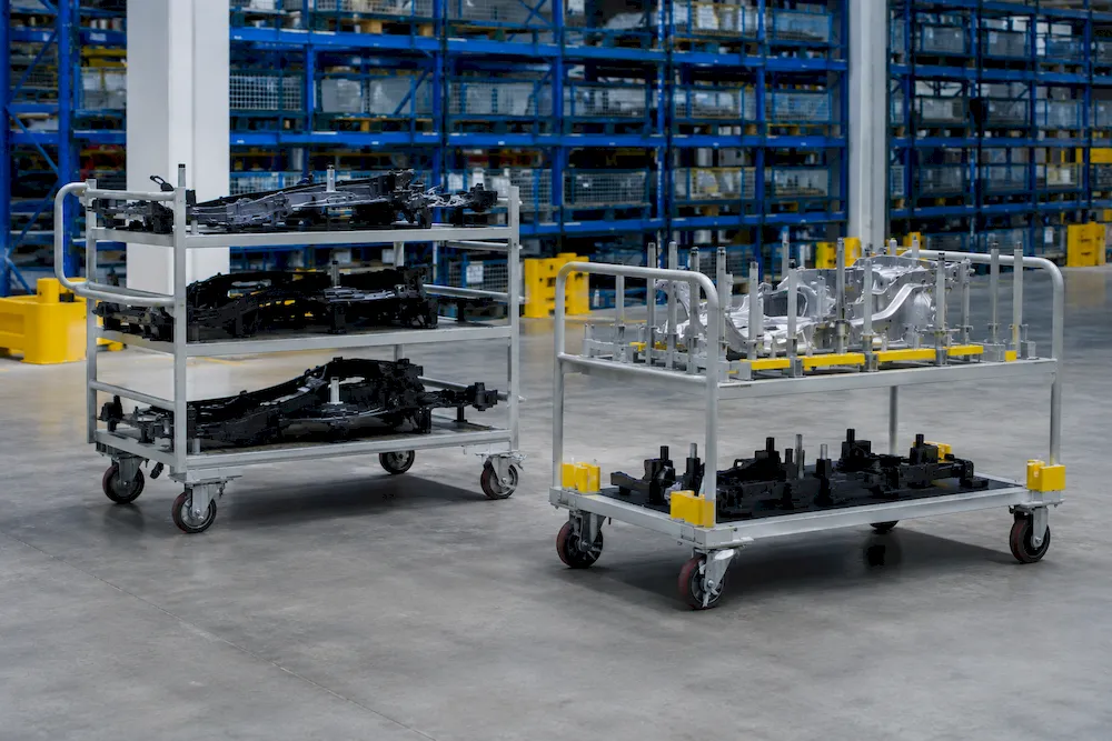
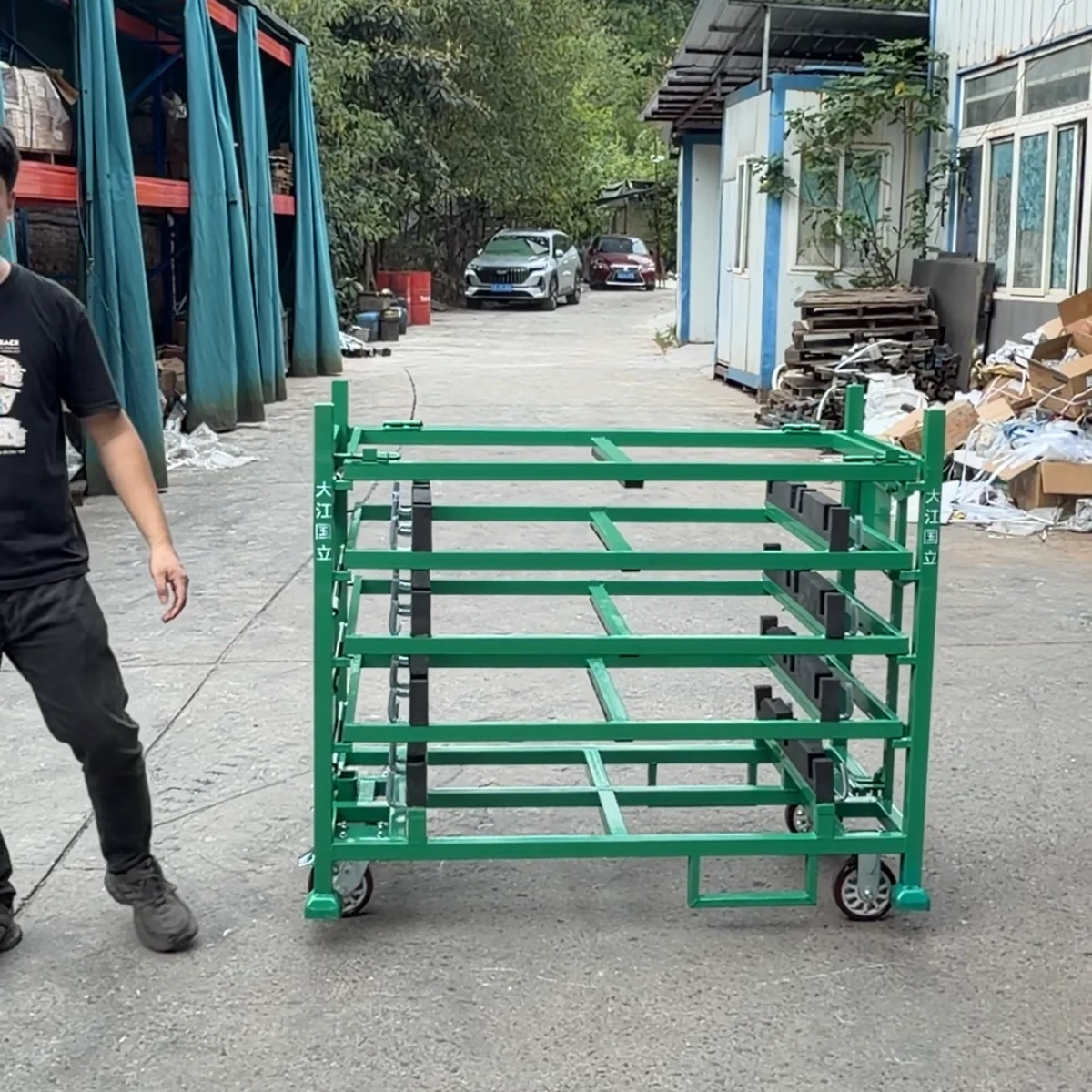
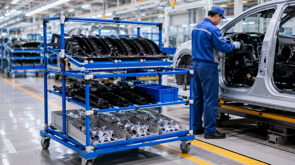
A custom electric compressor assembly logistics trolley for repeat movement between production, inspection and assembly. Multi-level part trays, protective side panels, casters and forklift pockets are configured around the compressor geometry, handling route and required quantity per trolley.
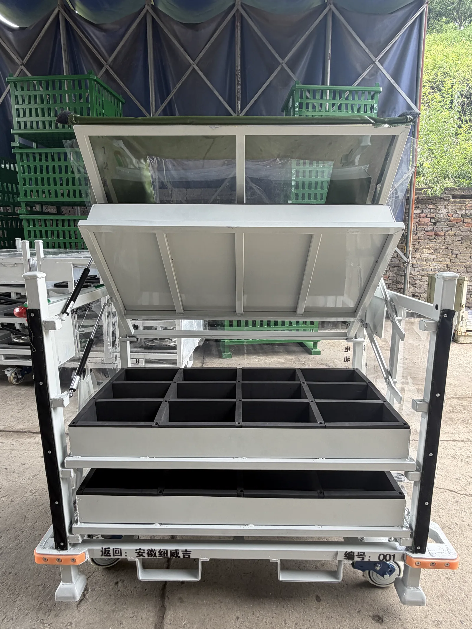
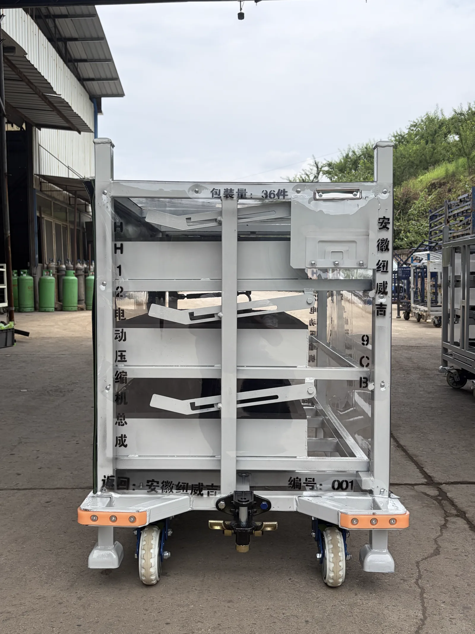
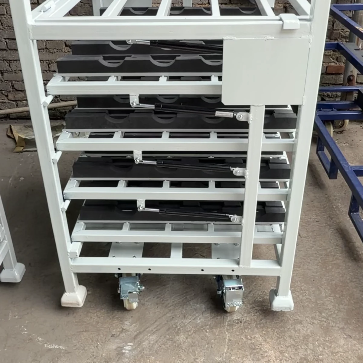
This real electric compressor assembly trolley combines multi-level opening trays, protected part positions, industrial casters and forklift pockets. Select the final layout from the compressor CAD, permitted support zones, connector clearances, loading sequence and complete plant route; send those inputs with trolley quantity and destination for a custom quotation.
At a Glance
- Structure
- Custom welded steel trolley with multi-level trays
- Part retention
- Part-specific locators, dividers and non-metal contact protection
- Handling
- Industrial casters, forklift pockets and tow interface as required
- Protection
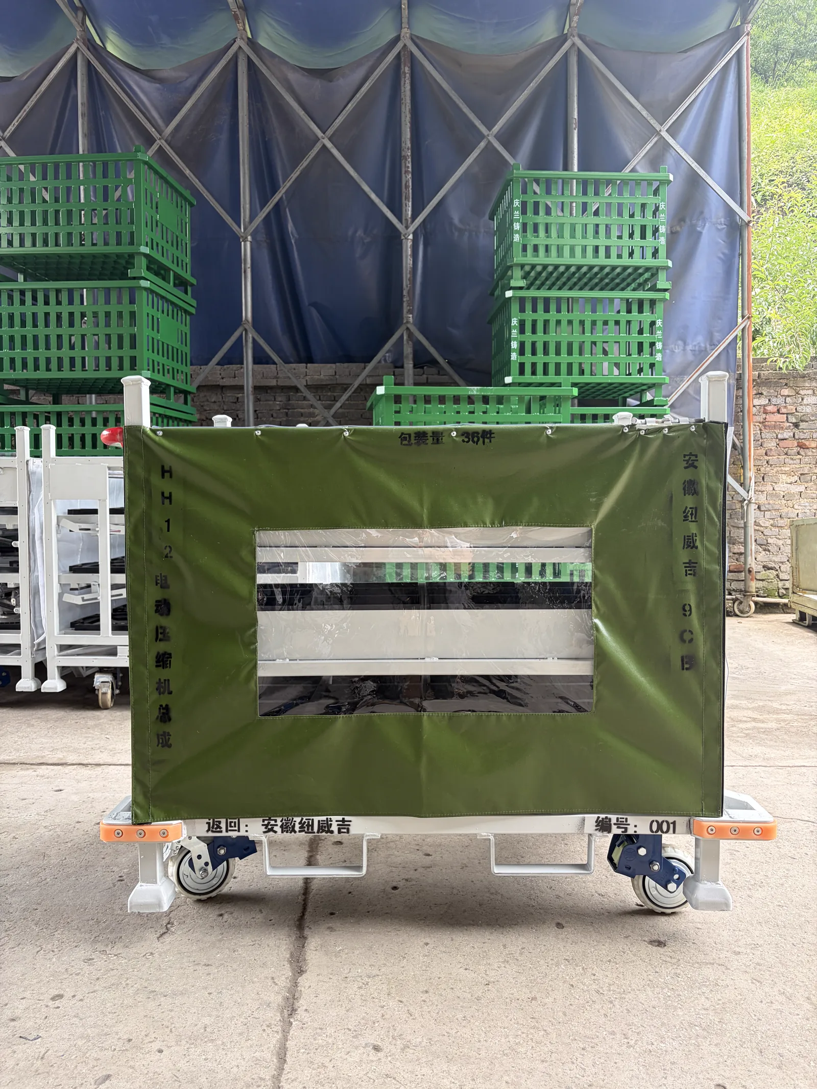
- Optional fabric, clear-panel or solid protective cover
- Capacity
- Specified to assembly weight and required quantity per trolley
- MOQ
- Typically 20–50 units; trial orders available
- Lead time
- Historical planning reference: sample about 7–15 days; production about 25–45 days. Reconfirm for each quotation.
Built example
Product Gallery
Real photos of a custom-built configuration. Dimensions, part count and handling details are specified for each buyer's programme.
Description
An electric compressor assembly logistics trolley is a returnable steel carrier built around the compressor assembly, its contact points and the way it moves through a factory. This photographed configuration uses multiple part positions, protective panels, industrial casters and forklift pockets so a buyer can define access, protection and handling as one system rather than buying a generic cart.
It is suited to OEM and Tier-supplier programmes that need repeatable transfer between machining, assembly, inspection, warehouse and line-side operations. The final footprint, tray count, dunnage, wheel specification, cover and load rating are confirmed from the actual compressor drawing, assembly weight and route.
What the trolley is designed to solve
- Hold each compressor assembly in a defined position with part-specific trays and locators
- Protect sensitive surfaces and connections with replaceable non-metal contact materials where required
- Support manual movement on casters, forklift transfer, or towable logistics routes as specified
- Provide clear operator access to multiple levels without mixing parts
- Use a reusable frame for repeat internal or supplier-to-plant movements
Configuration options
| Design input | What we configure |
|---|---|
| Assembly drawing, weight and centre of gravity | Frame structure, tray orientation and retention points |
| Parts per trolley and line-side presentation | Level count, tray spacing and loading sequence |
| Handling method | Casters, brakes, forklift pockets, tow bar or docking features |
| Surface and connection protection | EVA, rubber, plastic blocks, fabric panels or other dunnage |
| Return loop and storage condition | Stacking, nesting, protective cover and finish selection |
Start a compressor trolley project
Send the compressor assembly drawing or photos, part weight, target quantity per trolley, handling route and destination. HAOFU will turn those inputs into a custom rack brief, build a sample for fit and handling review, then manufacture the approved design in China for worldwide shipment. For a broader selection framework, see our material handling trolley guide and automotive parts rack design guide.
Configuration comparison
Which compressor trolley layout fits the handling task?
The useful choice is not simply the highest tray count. Compare how the assembly enters each position, how connectors stay clear and how the trolley moves between inspection, storage and line-side use.
| Configuration | Use it when | Main trade-off | Send with the RFQ |
|---|---|---|---|
| Fixed multi-level positions | Every compressor follows the same orientation and the operator can reach each level without moving another tray. | Simple repeated presentation, but upper levels can restrict access if tray pitch and loading motion are not checked together. | Part envelope, allowed supports, connector keep-out zones, loading side and required units per level. |
| Opening or tilting tray levels | A lower position needs extra vertical clearance during loading or removal. | Improves access to selected levels while adding hinges, stops and an opening sequence to the trolley. | Loaded tray mass, opening angle, operator reach, hold-open requirement and closing sequence. |
| Covered mobile trolley | The route benefits from side panels or a cover together with manual movement and forklift transfer. | Adds enclosure and flexible handling; cover access, visibility, wheel state and fork clearance must remain compatible. | Exposure condition, access window, route surface, caster/brake preference and fork tine details. |
From requirement to quotation
Prepare a compressor assembly trolley RFQ
Use the actual component and route to turn a photographed reference into a trolley concept that can be priced and reviewed.
- 1
Map the assembly
Send CAD, mass, centre of gravity, approved supports and no-contact connectors or machined faces.
Output: Part contact map
- 2
Set the tray sequence
Show loading side, orientation, units per level and the motion needed to reach every position.
Output: Tray and access layout
- 3
Walk the route
List floor joints, turns, parking, manual movement and every forklift or tugger hand-off.
Output: Caster and base interfaces
- 4
Request the custom quote
Add trolley quantity, destination, identification and sample-review expectations.
Output: Comparable trolley proposal
Guides & Resources
Learn more about choosing and using electric compressor assembly logistics trolley.
Applications, Engineering & Buyer Tools
Move from product discovery to a project specification, application check and inspection plan.
Electric Compressor Assembly Logistics Trolley — Frequently Asked Questions
Can the trolley be designed for our electric compressor assembly?+
Yes. Send the assembly drawing, weight, centre of gravity, sensitive connection points, quantity per trolley and loading direction. We design the trays, locators, frame and protective contact points around the approved component.
Can the trolley use both casters and forklift pockets?+
Yes. We can combine industrial casters for controlled in-plant movement with forklift pockets for warehouse transfer. Brakes, fixed/swivel wheel arrangements and tow interfaces are selected for the actual route and floor condition.
How is the part protected in transit?+
Protection is designed at each contact point. Depending on the assembly, this can include EVA, rubber, plastic blocks, fabric panels, dividers or a cover. The aim is to prevent movement and metal-to-part contact, not simply to add packaging.
Do you build a sample before production?+
Yes. Once the part data and concept are confirmed, a tested sample normally takes about 7–15 days. It lets the buyer review fit, access and handling before a volume order is released.
What information is needed to quote a compressor trolley?+
Provide part drawings or photos, assembly weight, quantity per trolley, loading direction, handling method, route, expected order quantity and destination. We then confirm the appropriate configuration and quotation.
Discuss your part or handling task
Send a photo, drawing or short description to start your enquiry.
Contact Us Now