
Application
Automotive Engine Racks
Automotive engine racks are part-specific steel carriers used to present, move, store or return engine assemblies within a defined logistics process. The rack is not selected from a universal load table: support points, centre of gravity, access, handling equipment and route conditions must be confirmed for the actual engine and project.
Reviewed by Ms. Zhao · Last reviewed 2026-09-02
Direct answer
A custom automotive engine rack should locate the approved engine at controlled support points while providing the required fork, crane, conveyor or manual access. The buyer should provide the engine drawing or sample, loaded mass and centre-of-gravity information, loading method, route, stacking condition and contact restrictions before the rack is designed and validated.
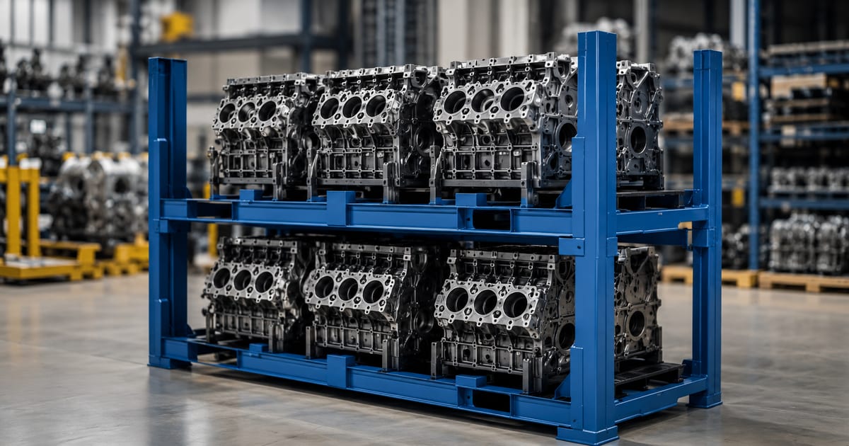
What the rack must accommodate
The steel frame, locating features and dunnage are developed around the actual engine assembly and its approved contact zones.
- Engine envelope and permitted support points
- Loading and unloading direction
- Fork, crane, conveyor or line-side interfaces
- Stacking state and return condition
- Drainage, cleanliness, label and identification needs
Protection and access decisions
Protection is not only a choice of padding. The project must control contact location, part movement, operator access and any removable or moving fixtures throughout the route.
Engine-rack specification decisions
Use this matrix to identify required project inputs. It does not publish universal dimensions, load ratings or tolerances.
| Decision | Guidance | Buyer input |
|---|---|---|
| Part definition | Use the approved engine drawing, sample or controlled envelope. | CAD/drawing, mass, centre of gravity, contact restrictions |
| Loading method | Keep required access clear and define the loading sequence. | Crane/fork/manual/robot method and direction |
| Handling interface | Match fork pockets, conveyor datum or tugger interface to the actual equipment. | Equipment drawing or interface manual |
| Stack and return | Confirm loaded stacking and empty-return conditions separately. | Stacking state, return ratio and transport envelope |
Project workflow
- 1
Define the engine
Provide the controlled drawing or sample, mass, centre of gravity and permitted contact points.
- 2
Map the handling route
Record every loading, storage, transfer and unloading interface.
- 3
Approve the design inputs
Confirm access, dunnage, stacking, identification and return requirements before sample manufacture.
- 4
Validate the sample
Use the agreed inspection and validation plan with the actual part and handling equipment where available.
Start an engine-rack design review
Send the engine drawing or sample information, load case, handling interfaces and route requirements for an engineering review.
Send drawings or requirements