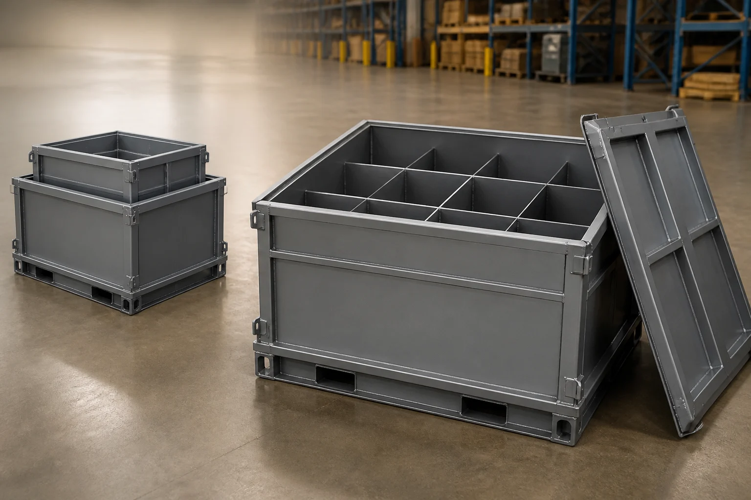
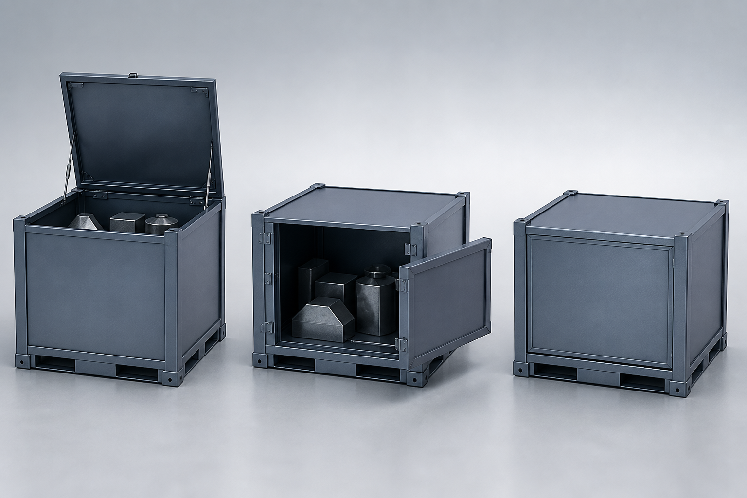
Metal Container Dividers: Plan the Part and Insert Exit Paths

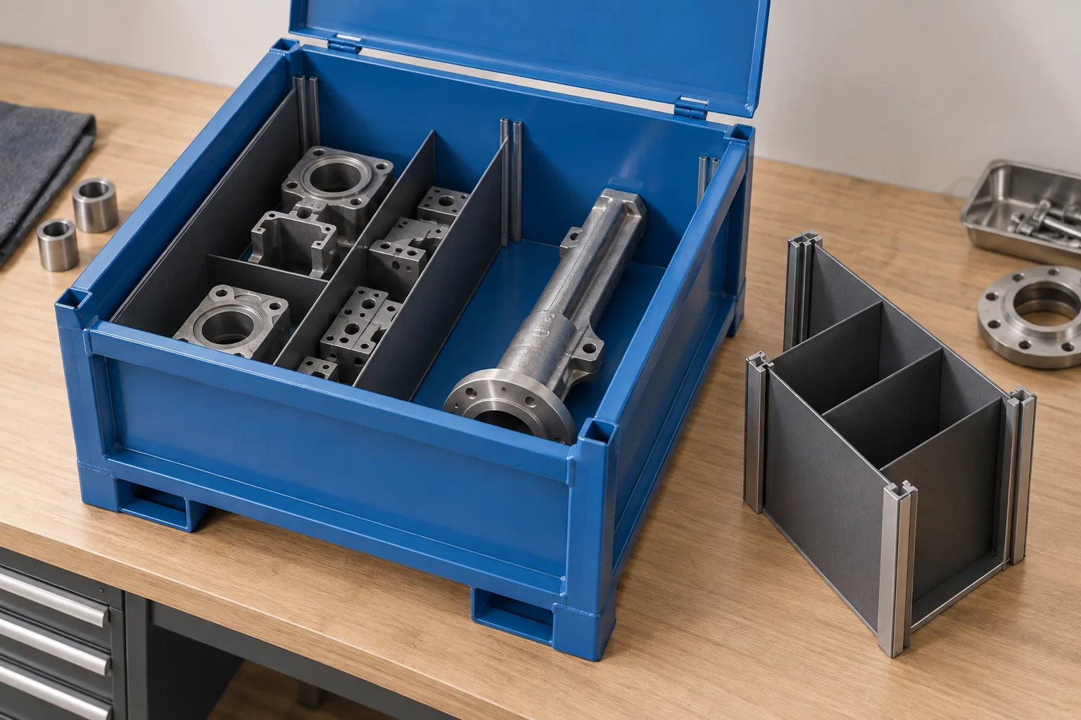
Choose internal metal-container dividers by tracing the first and last part out of the box. If each part clears a low fixed divider, part-first unloading keeps the divider in place. If the insert blocks the part's exit, a lift-out partition may work—but it needs a grasp point, clear lift route and somewhere to rest during unloading. Send the supplier part CAD, orientation, sequence, operator or lifting-device access and the forklift handling envelope.
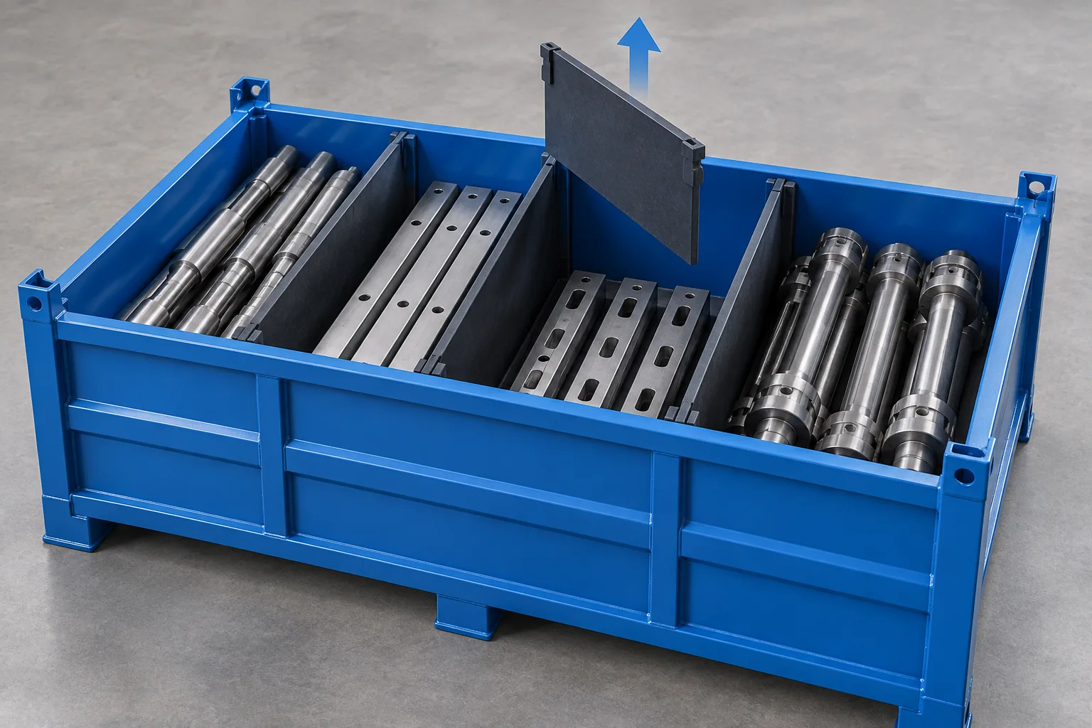
For a metal parts container with internal dividers, decide what leaves first: the part or the insert. If a part can be gripped and lifted clear of a low fixed divider, the divider may stay in the box throughout unloading. If the divider blocks that motion, a lift-out insert can create a larger exit path—but someone must reach it, lift it and set it down. Draw the first and last part paths at the work cell, then check that the chosen divider remains located while the closed container travels by forklift.
Imagine several long metal assemblies in adjacent compartments. The first assembly may lift cleanly, while the last is trapped against a side wall or under a partition lip. A plan-view divider drawing misses the hand position and vertical exit envelope. Lowe's sheeted-stillage range shows fixed and removable partitions as real configuration choices; the next question for this buyer is how a loaded container actually empties.
Start with the first and last part
Mark each part's orientation and where an operator or lifting device can grasp it. Draw the swept shape as it rises and turns, including a glove, lifting fixture or protective wrap if used. Then repeat for the final part when the neighboring cells are empty. Record the container height at the unloading station; a divider that is easy to remove on the floor may be awkward at bench height.
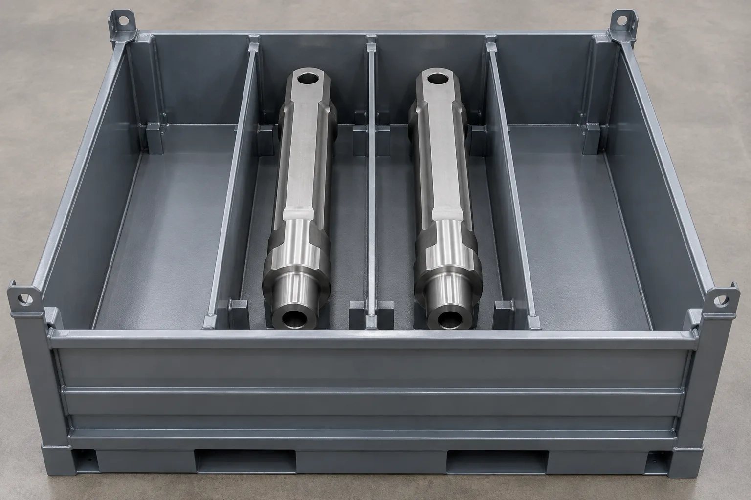
Part-first or divider-first unloading?
Use if each part clears its cell. Check last-part grip and lift height; divider stays in the container.
Use if the insert blocks the part path. Check its grip, lift route and temporary placement.
A fixed low divider avoids handling a loose component and may suit repeatable part-first lifts. A lift-out insert works when removing it frees the part path and its own lift can be performed at the station. If the insert is loaded or tied to the parts, include that state in the handling trial. Nefab's steel-packaging overview shows modular inner trays inside a steel outer container; ask whether that kind of insert can actually leave before your part does.
| Input | Decision it informs | Show on drawing |
|---|---|---|
| Part CAD, mass and orientation | Whether the part clears its compartment without rotation. | First/last part exit silhouettes. |
| Grasp or lifting fixture | Whether hand or device reaches past a divider. | Grip zone and vertical lift envelope. |
| Unload order and cycle | Whether a fixed divider can stay or an insert must come out first. | Numbered removal sequence. |
| Insert handling | Whether a removable partition is manageable at the workstation. | Handle, lift route and temporary set-down area. |
| Fork route and storage state | How inserts and parts remain located during transport. | Fork entry, base clearance and closed travel condition. |
Test the entire sequence at the work cell
- Mark exit silhouetteDraw the first and last part paths.
- Does the part clear?Yes: test part-first removal with fixed divider.
- If no, lift the insertCheck grasp, lift and set-down space.
- Trial the full routeUnload, reinsert, close and fork-move.
- Draw the first and last exit paths. Use representative parts, current CAD, lifting fixture and the planned container height.
- Try part-first removal. Check whether a low fixed divider permits grip, lift and any necessary rotation without snagging.
- If blocked, trial divider-first removal. Locate the insert grip, lift route and set-down space; check the part path after it leaves.
- Repack and move. Put the insert and parts back in their travel positions and check the closed container's forklift approach and retention.
- Put the chosen sequence on one drawing. Number the moves and show the divider, lifting access and fork interface together.
For a broader fixed-versus-removable interior overview, see the container configuration guide. For a wall or door opening, use the access-panel guide. The metal-versus-plastic guide addresses container material selection, not this unload sequence.
Request a container layout around the exit path
HAOFU can develop a custom metal container with internal partitioning around the parts and handling task. Send part CAD or samples, orientation and quantity per box, first/last pick video or sketch, lifting device, station height, insert set-down space, forklift entry direction and required quantity through the metal-container engineering RFQ. Request both the loaded travel view and the numbered unload view.
Frequently Asked Questions
- Should parts or dividers leave a metal container first?
- Start with the part-first route. If the first and last parts clear the dividers with a practical grip and lift, fixed low dividers can stay. If an insert blocks the path, trial removing it first and plan its set-down position.
- When is a removable divider useful?
- It is useful when lifting it creates a workable part exit path and the insert itself can be grasped, lifted and placed at the work cell. Test it in the intended loaded state.
- What can make the last part harder to remove?
- The final part may sit against a side wall or under a divider lip after neighboring parts are gone. Draw its full swept lift shape, not just the compartment footprint.
- Does an insert change forklift handling?
- It can. Show how the insert and parts remain located in the closed travel state, and include the fork entry and base clearance in the same container drawing.
- What belongs in a metal-container divider RFQ?
- Send part CAD or samples, mass, orientation, quantity per box, first/last removal sequence, grip or lifting fixture, station height, insert set-down space and forklift approach.