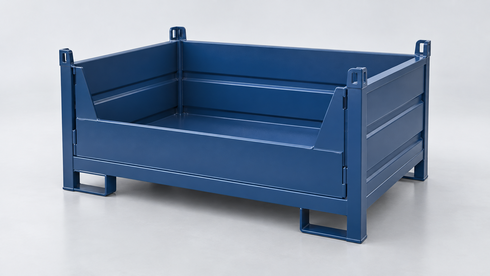
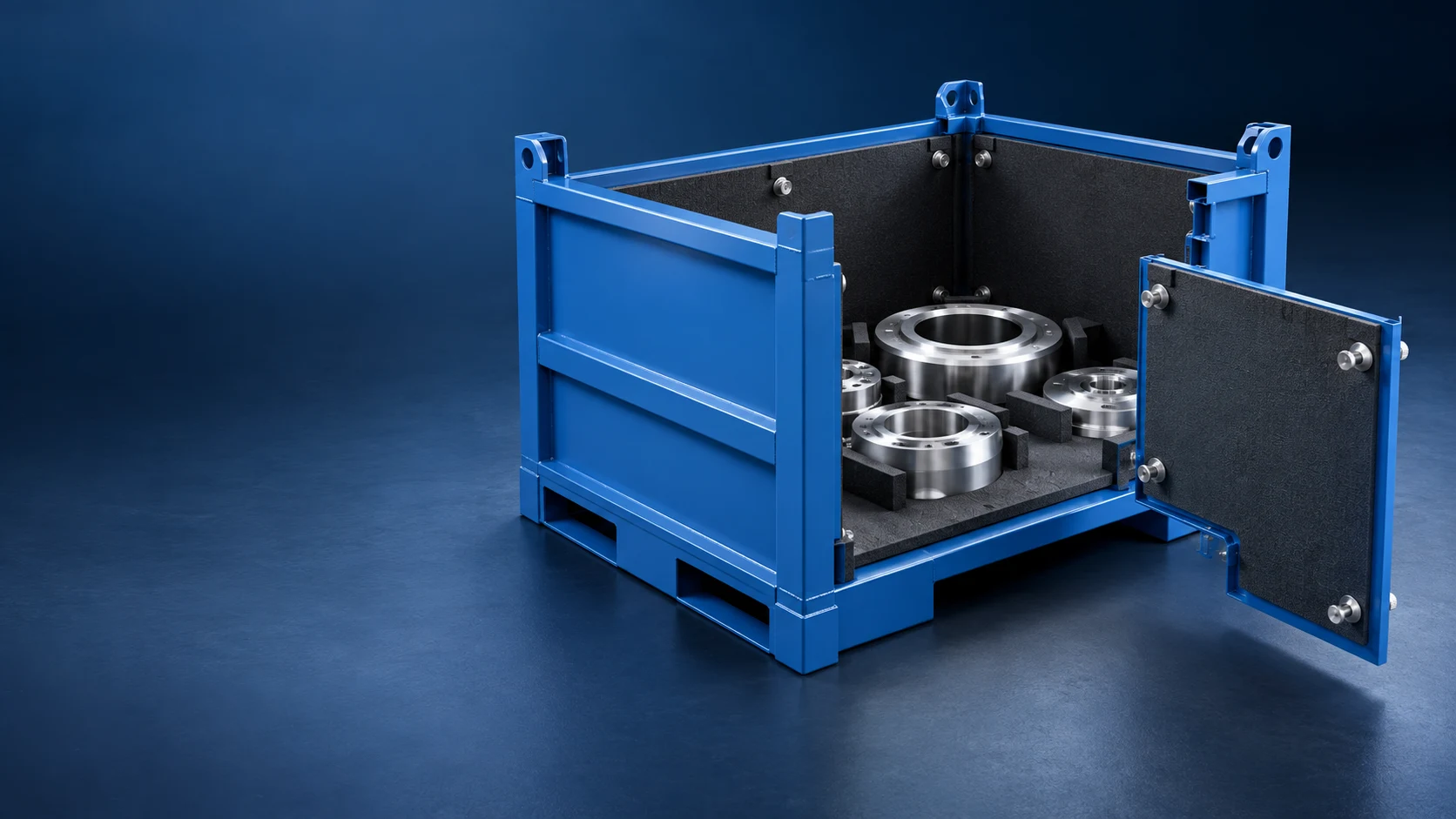
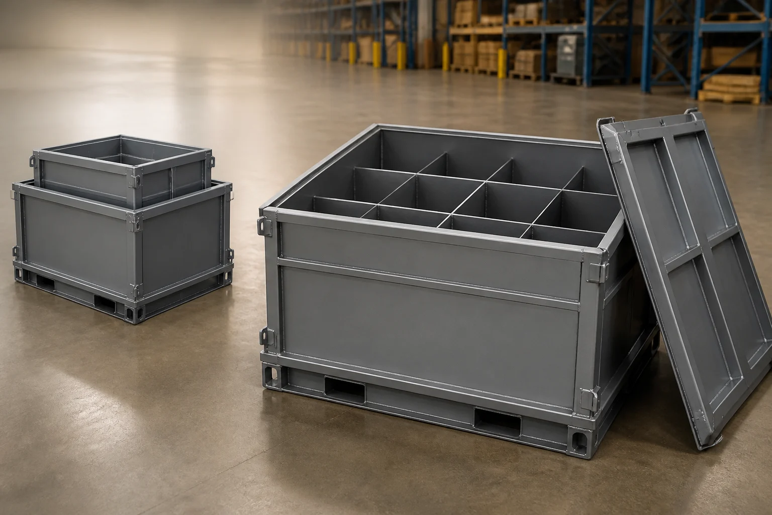
Custom Metal Container Drainage: Choose a Drain Path, Sump or Removable Tray

Choose the drainage or collection route from what enters the container and when it may be removed. Map oil, wash water and chips separately; show loading, transport, washing and service orientations; then select a controlled drain point, fixed collection area or removable tray. Keep the route clear of part supports, fork pockets and stacking features, and make screens, plugs and trays accessible. Send the container supplier the residue state, part and support drawing, service position, fork interface and maintenance sequence.
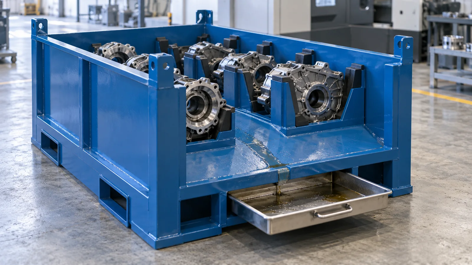
Choose custom metal container drainage from the real residue and service sequence, not from a standard drain-hole detail. First separate free liquid from chips, swarf or packaging debris. Then show when the container is level or tilted, whether liquid must remain captured during transport, and where an operator can safely drain, remove or clean the collection feature. A controlled outlet suits a defined service position; a fixed sump keeps the low point in the container; a removable tray gives the collected material its own removal path. In every case, part supports, fork pockets, runners and stacking features must remain clear.
Commercial products illustrate the available building blocks. Ragnar Rescue combines a mesh box with a sealed removable drip tray, while Pierce Steel offers fabricated pans with options such as drain couplings and sumps. PROCECO shows how returnable containers can pass through dedicated washing equipment. These examples are useful interface references, not HAOFU specifications. The buyer still has to define the residue, route and maintenance task for the custom container.
Define what the container receives
Oil carried in from machining, rinse water left after washing and metal chips behave differently. Free liquid follows gravity. Thick fluid may drain slowly. Fine chips can move with liquid and block a small outlet, while larger swarf can bridge a screen or become trapped under a support. Packaging fragments may float or adhere to a tray. Record the likely combinations instead of describing everything as “dirty water.”
The amount and timing matter to configuration selection. A few drops that must stay off the floor suggest a different collection task from a container deliberately washed between loops. Show whether residue enters continuously during loading, appears only after washing, or can be present through transport. If the liquid has site-specific handling rules, include those rules in the project input; the steel container alone does not determine how the material is disposed of.
| Operating condition | Configuration to examine | Key interface | RFQ evidence |
|---|---|---|---|
| Small amount of liquid, removed at one service point | Sloped or directed floor with controlled drain point. | Accessible outlet, plug or valve; debris kept upstream. | Service pose, permitted outlet side and expected residue. |
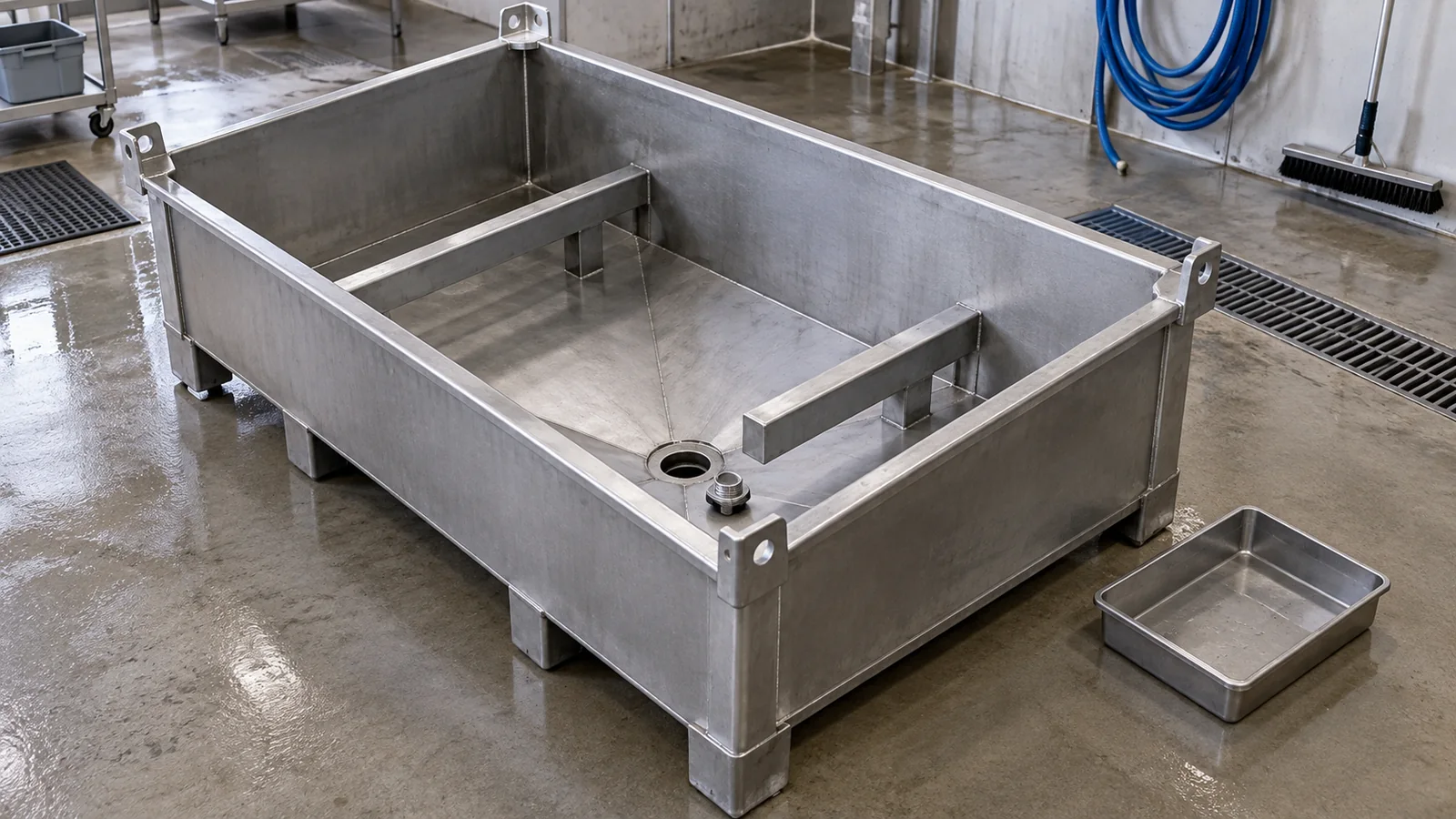
| Liquid must remain in the container until maintenance | Fixed low point or collection sump with cleanout access. | Part supports bridge the collection zone; inspection remains possible. | Expected volume, access tool and emptying method. |
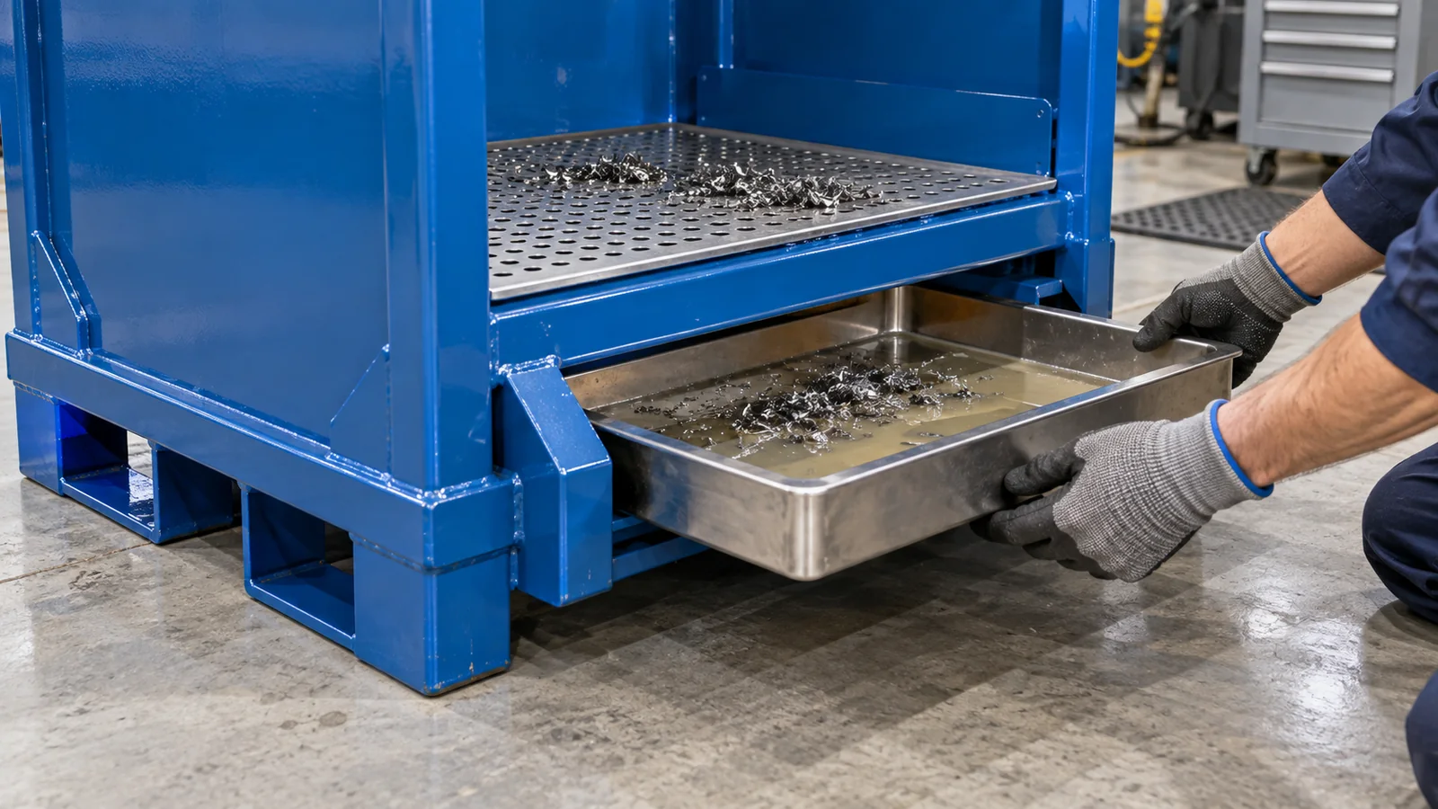
| Liquid or debris is carried out separately | Removable tray or false floor over a collection tray. | Tray grip, slide path, retention and spill-aware emptying task. | Removal side, operator clearance and tray service route. |
| Liquid and chips arrive together | Screen, perforated deck or removable separator before the collection point. | Screen removal and cleaning without disturbing dunnage. | Chip size/shape, liquid behavior and cleaning frequency. |
| Container changes orientation during washing | Drain paths checked in every wash and dry position. | Tubes, folds and supports do not create unintended pockets. | Washer envelope, spray direction and container orientation. |
Use when liquid may leave only at a defined service position. Show the plug or valve access and keep chips upstream.
Use when liquid remains in a low point until the container reaches a maintenance task. Preserve cleaning and inspection access.
Use when the collected liquid or debris must be carried out separately. Define the grip, slide and emptying path.
Keep the collection route separate from part support
The floor feature cannot be designed in isolation from the payload. Mark every approved part-contact zone and every no-contact surface on the component drawing. Supports should carry the part through deliberate load paths while leaving liquid a route toward the chosen low point. Avoid making the removable tray the accidental structural support unless that function is explicitly designed and reviewed.
Use sections through each support station. These reveal pockets created by brackets, overlapping plates or dunnage bases that a plan view can hide. A simple downward path also helps the operator see and reach collected debris. When the part itself blocks the route, consider separate channels between support stations rather than one unobstructed floor assumption.
Give chips and debris their own removal task
A drain opening that passes liquid can still fail the maintenance task when swarf covers it. If chips are expected, decide whether a removable screen, perforated false floor or lift-out insert should intercept them. The feature must come out without lifting the payload through an unsafe motion or dismantling unrelated parts of the container. Mark how the operator grips it, where residue can fall during removal and where the cleaned component returns.
The UK HSE's current MW5 metalworking-fluid guidance emphasizes appropriate equipment, cleaning and spill management around metalworking fluids. Use the site's own fluid and waste procedures to define the task; do not transfer a generic chemical compatibility or disposal claim to the container design.
Design the tray, plug or cleanout for access
Access determines whether the collection feature will be used. A side-pull tray needs clearance for its full length plus a grip that remains reachable when the container is staged. A drain plug or valve needs tool and hand clearance in the service orientation. A fixed sump needs an opening large enough for the site's removal method and a way to inspect the low point.
Check retention in every non-service state. A tray should not migrate into a fork path or leave the container during normal handling. A plug should not become the first contact point when the container is set down. Service hardware should also remain clear of stacking feet, locating cones and other containers placed beside it.
Review every container orientation
A floor slope works only relative to gravity in the intended pose. Overlay the container in loading, forklift pickup, transport, washing, draining and empty storage positions. If the washer rotates or tilts the container, identify the temporary low points. Check closed tubes, gussets, folded edges and dunnage fasteners for places where water or chips can collect.
Also examine the bottom frame. Fork pockets and runners need structural continuity and usable entry, while a low sump or tray needs space and protection. Coordinate these features on one cross-section rather than resolving the top tray and fork base as separate projects. For the wider washing discussion, use the custom metal container cleaning guide; this page focuses on the physical drain and collection route.
- Define the residueDescribe oil, water and debris separately, including when and where each appears.
- Map the container orientationsShow loading, transport, washing, draining, emptying and maintenance positions.
- Choose a drain or collection routeSelect a controlled outlet, fixed sump or removable tray from the site task.
- Protect structural and handling interfacesKeep the route clear of part supports, fork pockets, runners and stacking features.
- Trial the service taskUse representative residue to check access, separation, emptying, cleaning and inspection.
Five steps to prepare drainage and collection inputs
- Describe the residue by state. List free liquid, viscous oil, chips, swarf and packaging debris, including when each enters the container.
- Draw every relevant orientation. Show loading, transport, washing, draining, emptying and maintenance positions.
- Select a collection route. Compare a controlled outlet, fixed low point and removable tray against the site's service task.
- Coordinate supports and the base. Keep the route clear of part-contact stations, fork pockets, runners and stacking locators.
- Trial representative service work. Check separation, access, removal, cleaning and inspection with representative residue before production release.
What to send for a custom metal container quote
Send the part drawing or sample, permitted contact zones, container orientation at each step, likely liquid and debris, whether residue must stay captured in transport, washing and drying method, preferred service side, outlet or tray constraints, fork and stacking interfaces, quantity, destination and acceptance task. Review custom metal containers from a China-based manufacturer, then send the part and process inputs for an engineering quotation. A clear service sequence lets the supplier price a useful collection route instead of guessing at a drain detail.
Frequently Asked Questions
- Should a custom metal container use drain holes or a removable tray?
- Use a controlled drain point when liquid can leave at a defined service position. Use a removable tray when the collected liquid or debris needs a separate carrying and emptying route. The choice depends on transport containment, residue and maintenance access.
- Can one container handle both oil and metal chips?
- It can be designed with a screen, perforated false floor or removable separator ahead of the collection point. Share the chip size and shape, oil behavior, cleaning frequency and removal task so the two materials do not simply block the same outlet.
- Where should the drain point be placed?
- Place it at the low point in the actual service orientation, on a side the operator can reach, and away from part supports, fork paths, runners and stacking contacts. Check every wash and transport orientation before fixing the location.
- Will a sloped floor interfere with part supports?
- It can if both are designed separately. Map approved support zones first, carry those supports into the base structure and route liquid around or between them using coordinated sections.
- How do you keep drainage clear of forklift pockets?
- Overlay the drain, sump or tray envelope with fork entry, cross-members, runners and pickup clearance. Keep service hardware protected and accessible without narrowing the intended fork interface.
- What should I send for a custom metal container drainage quote?
- Send part CAD, contact restrictions, liquid and debris details, container positions during use and washing, service side, tray or drain preference, fork and stacking interfaces, quantity, destination and a representative maintenance task.