Metal Container Liner Service Access: Design the Changeout Path First

A protective liner should be selected from the service task as well as the part-contact layout. First draw how parts enter, rest and leave the metal container. Then draw how the liner is inspected, released, removed, set down and refitted—whether the container is loaded or empty. A fixed liner can suit an infrequent service task with reachable attachments; a captured panel can work when an open side provides a defined release path; a lift-out insert needs practical grip, lift and retained-travel details. Send the part surfaces, container opening, service frequency, attachment access and handling route with the RFQ.
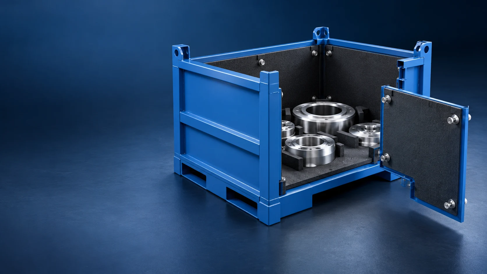
Draw the liner’s service route before choosing how it attaches inside a metal container. The part route answers how a component is loaded, supported, gripped and removed. The service route answers how a liner is inspected, released, lifted or slid out, set down and refitted. A fixed liner can be practical when fasteners are reachable and changeout is infrequent; a captured panel suits a usable opening and defined release direction; a lift-out insert needs a real grip, lift and travel-retention plan. Send the part’s permitted and restricted contact zones, the container opening, the expected service state and the handling route so the internal interface can be designed around the task.
Competitor pages usefully establish that access and internal protection belong in a custom container brief. Basin Industries groups access, handling and protective contact surfaces in its container scope. Morrison Industries starts container design from the load, handling, access and dunnage question. Gitterbox Nordic presents access sides, bases and inserts as configurable inputs. The buyer still needs one additional drawing: can the liner be serviced without crossing the part’s loading path or losing a practical way to handle the removed module?
Keep the part path and the liner service path separate
It is tempting to use the same opening for every task. That can be efficient, but it is not automatic. The part may need a broad, low-friction removal path while the liner needs a tool path behind a rail, a release edge clear of a side panel, or a set-down place at the work cell. Draw both movements in profile and plan view before deciding whether the liner stays fixed, comes out as a panel or lifts out as an insert.
| Liner arrangement | Useful starting condition | Decision to prove |
|---|---|---|
| Fixed liner | The liner stays in one location and service is infrequent. | Attachments, tool approach and replacement edge remain reachable without damaging adjacent interfaces. |
| Captured or guided panel | A side, door or panel can be opened to create a defined release route. | The panel has a clear release direction, retention in travel and practical set-down space after removal. |
| Lift-out insert | An empty or otherwise safe service state allows the whole liner module to be removed. | Grip, lift method, module handling, refit alignment and retained transport state are defined. |
| Multiple service zones | Only selected contact areas are expected to be serviced. | Each zone is identifiable and can be reached without turning the container into a generic divider layout. |
Use a stable interface when service access can reach the fasteners and the replacement task is infrequent.
A panel can slide or lift from guides when the container has a practical open side and defined release direction.
A whole liner module needs a practical grip, lift, set-down and retained travel state—not just a removable drawing detail.
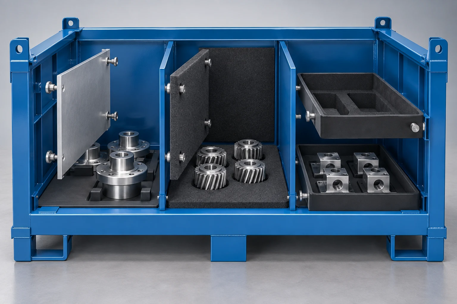
Fixed liners need a visible attachment and tool path
A fixed liner can keep the inside layout simple when the condition being serviced is local and the attachment is reachable. The useful question is not simply “can it be replaced?” Draw where a hand or tool approaches, what holds the liner while the attachment is released, and which edge leaves first. If the task needs the container empty, say so. If it must happen from one particular open side, put that on the drawing. This prevents a liner from being technically removable but impractical at the station.
Captured panels and lift-out inserts need a complete removal route
A captured panel can be a clean option when rails, slots or retainers guide the part of the liner that is meant to move. Give the panel a release direction that does not conflict with the container wall, a door, the part path or a nearby workstation. A lift-out insert adds another decision: after it leaves the container, how is it gripped, carried and positioned for service, and how does it stay located during the normal travel state?
Do not turn this into a generic divider comparison. the divider unloading-path guide helps decide whether the part or an insert should leave first during routine picking. This page is narrower: it owns the maintenance access and attachment route for a liner after the buyer has decided the container requires a serviceable internal contact interface. For material/part-contact component sourcing, explore components and dunnage alongside the complete-container decision.
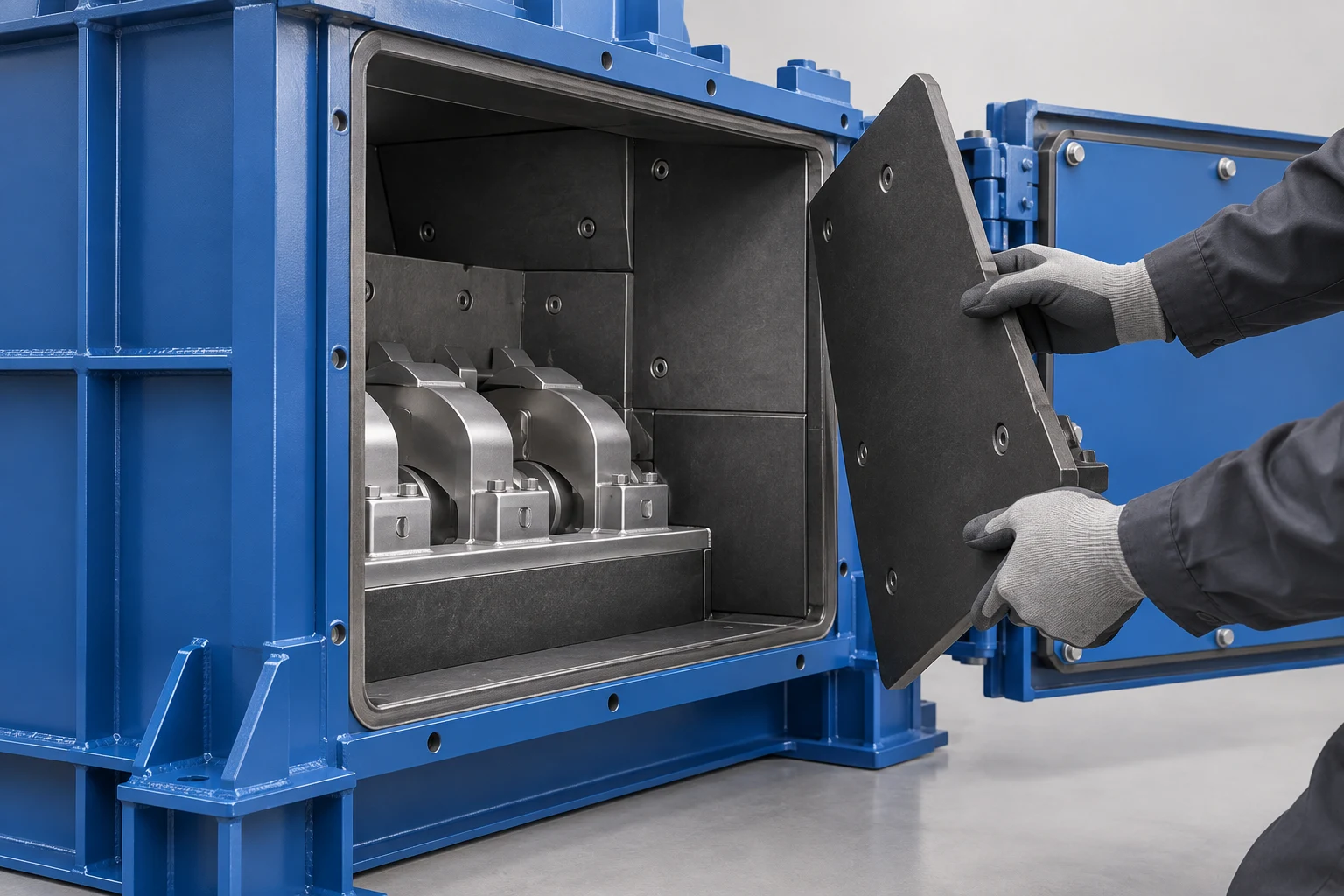
Put service information into the RFQ, not only into a maintenance note
The container supplier needs the service task early enough to protect the required opening, attachment points and clearance. Include the part’s allowed and prohibited contact areas, how often the liner is expected to be inspected or changed, whether service is loaded or empty, the available opening, the hand or tool access, and what may be stored or removed during the task. A recent automotive-packaging update from Suppliers Partnership for the Environment highlighted circularity across the packaging life cycle, including repair and return. That context supports asking how a reusable container will be serviced; it does not define your liner, material, process or acceptance criteria.
- Map the part pathDraw how the part enters, rests, is gripped and leaves the container at the actual work point.
- Map the liner service pathIdentify whether service happens loaded or empty, from which side, with which hand or tool.
- Choose the attachment styleCompare fixed, captured and lift-out interfaces against the service frequency and reachable opening.
- Draw access and set-down spaceShow the release edge, tool clearance, removed-module handling and travel-state retention.
- Trial the service taskRemove, refit, close and handle a representative configuration before the production drawing is released.
Five steps to specify liner service access
- Map the part path. Show how the part enters, is supported, is gripped and exits at the real work point.
- Map the service path. State whether the liner is inspected or changed loaded or empty, from which side and with which hand or tool.
- Choose the liner interface. Compare fixed, captured and lift-out options against service frequency, opening geometry and handling.
- Draw removal and set-down. Show fasteners or retainers, release direction, clearance, grip, removed-module location and travel-state retention.
- Trial the complete task. Check removal, refit, closing and normal handling with a representative configuration before release.
What to send for a custom metal-container quotation
Send the current part CAD or sample; finish and permitted/restricted contact zones; quantity and orientation per container; container inside envelope and access side; loading, unloading and grip path; liner service frequency; loaded or empty service state; required hand or tool access; proposed attachment or retention preference; forklift, crane, trolley or conveyor interfaces; route; quantity; and the sample trial task. Review custom metal containers, then send the part, opening and service-path details for an engineering quotation.
Frequently Asked Questions
- When should a metal container use a removable liner?
- Consider it when the contact interface needs inspection or replacement and the container can provide a practical release, removal, set-down and refit route. The part path and service state should be drawn first.
- Can a liner be changed while the container is loaded?
- Only when the drawing provides safe practical access to the attachment or release path with parts present, and the task has been checked with the representative configuration. Otherwise specify an empty service state.
- What is the difference between a captured liner panel and a lift-out insert?
- A captured panel leaves through a defined guide or retainer path, usually from an open side. A lift-out insert removes as a module, so grip, lift, set-down and transport-state retention also need to be designed.
- Does a removable liner replace the need for internal dividers?
- No. A liner service interface and a divider layout solve different tasks. Decide the part's routine loading and unloading path separately, then make the selected liner practical to inspect or change.
- What should be shown on a liner service drawing?
- Show permitted and restricted part-contact zones, attachment or retention points, tool and hand access, release direction, clearance, removed-liner set-down location, open/closed container state and normal travel retention.
- What should I send for a custom metal-container liner quotation?
- Send the part drawing or sample, finish/contact restrictions, quantity and orientation, container opening, part path, service frequency and state, hand or tool access, handling route, quantity and sample-trial requirement.