One Trolley, Two Moves: Manual Push to Tugger Tow

A trolley used for both manual pushing and powered towing needs a defined stationary handoff, not just a handle and tow eye. Show where the operator parks it, how it is held while the tow bar is handled, where hands and feet are during coupling, and what changes before the tug moves. Then trial the loaded cart in both modes with the actual tug, floor and work-cell layout.
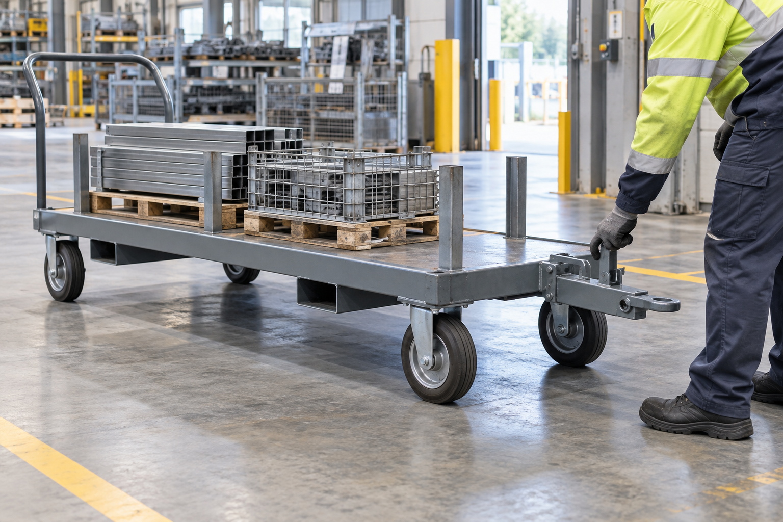
When one material-handling trolley is pushed by hand at a workstation and towed by a tug on the main route, design the stopped changeover as a separate task. Mark where the operator parks the cart, how it stays still, where the push handle and tow bar sit in each mode, and how the tug approaches without putting a person between moving equipment. The cart's wheels, brakes and load restraint must suit both movements. A tow eye alone does not establish a workable handoff, and a comfortable push handle alone does not establish towing compatibility.
Start with an actual route sketch: perhaps a short manual move into a cell, then a powered move between cells. WorkSafe Victoria's trolley guidance treats operator posture, floor, load, brakes and mechanical assistance as connected selection factors. The site owner should set the operating procedure; the supplier needs its physical inputs to propose a cart.
Where does the operator stand during each move?
One cart, two different movements
Operator at the handle for final placement. Check grip, sightline and wheel behavior; park before handling the tow bar.
Tug at the verified coupling height on a defined route. Check bar stow, coupling, braking and operator clearance.
For manual positioning, record the approach side, visibility over the load, grip location and distance to the nearest obstacle. For towing, record the actual tug, coupling location, travel direction and where a raised or stowed drawbar rests. At the changeover, the cart is stationary; the operator needs room to set or release the brake, move the bar, connect or disconnect, and step clear. Do not make the operator work in a gap that the tug or cart closes.
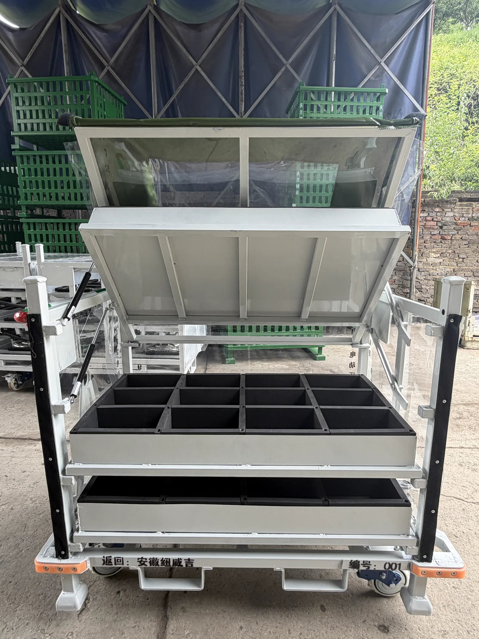
Put the stationary handoff on the cart drawing
| Handoff question | Site input | Cart drawing must show |
|---|---|---|
| How is it parked? | Transfer-bay position, floor slope, load state and site brake rule. | Brake or holding interface and operator access while stopped. |
| Where is the operator? | Push direction, handle grip, sightline and clear standing space. | Handle location and clearance from frame, wheels and drawbar. |
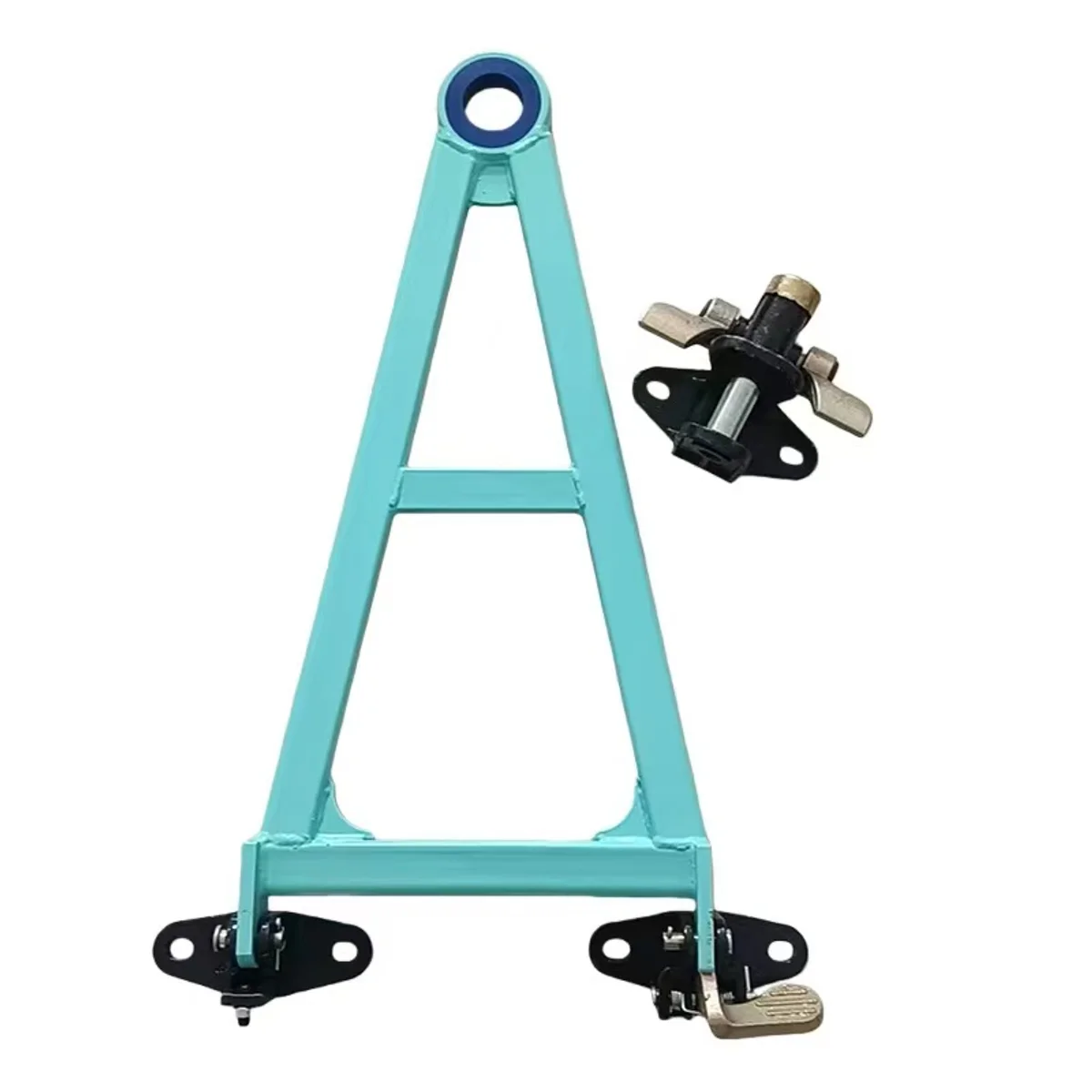
| How does the tug attach? | Real tug model, hook type, coupling height and approach. | Coupling envelope, bar travel/stow and connection access. |
| What changes when moving? | Loaded mass, wheel behavior, route surface, speed and stop points. | Wheel/caster arrangement and any mode-dependent restraint or brake state. |
| Who accepts the trial? | Operator, maintenance, tug owner and site-safety requirements. | Drawing revision and trial points for both directions and disconnect. |
Movexx's tug manual calls for a suitable hook, correct attachment height and a secure connection; these are requirements for its equipment, not proof that any HAOFU cart fits a given tug. A Creform product release illustrates that manual movement can be a designed mode on powered equipment, with its own mechanism. Do not transfer that mechanism or its ratings to an unreviewed trolley.
Trial the changeover before setting a fleet quantity
- Park the cartPosition, brake and load.
- Clear the operator zoneHandle, bar and feet.
- Connect to the tugHeight, latch and owner.
- Trial both modesMove, stop and disconnect.
- Map both jobs. Record the manual distance and placement task separately from the tug route, with load and floor conditions for each.
- Mark the handoff bay. Show the parked position, operator standing zone, tug approach and any nearby door, aisle or workstation edge.
- Review a combined drawing. Locate handle, bar, stow point, coupling, caster and brake on one loaded and empty cart layout.
- Trial the real sequence. Push, park, secure, connect, step clear, tow, stop, disconnect and push again using the actual tug and representative load.
- Close the issues. Have the site owners agree the physical changes and instructions before ordering the fleet.
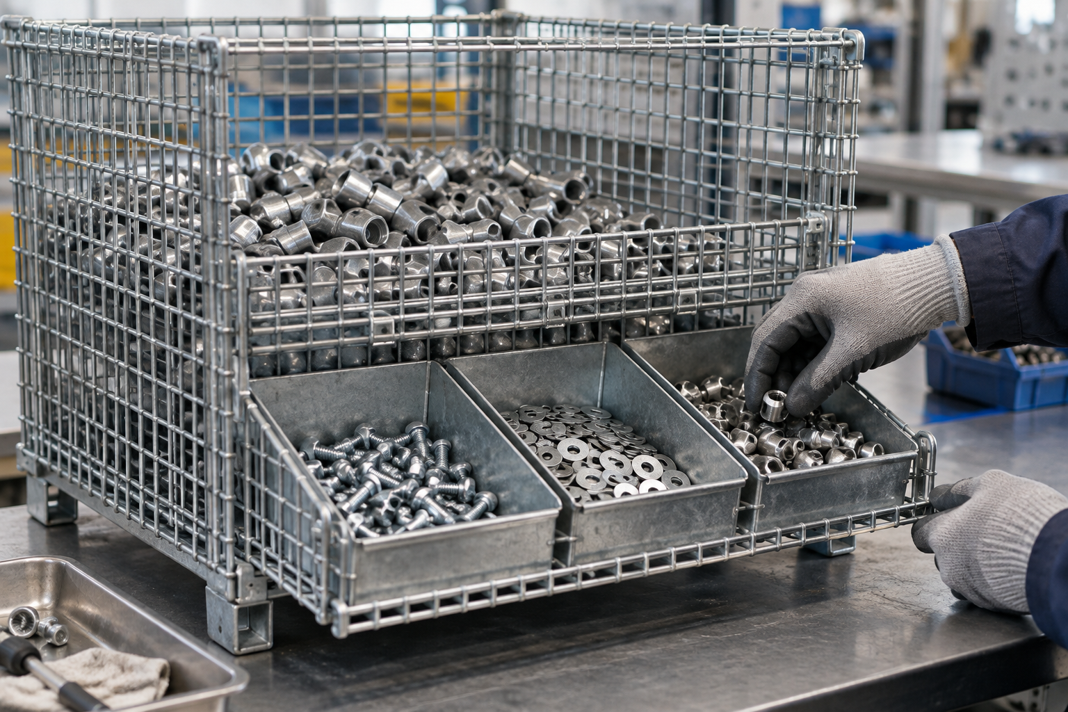
This is the changeover task, not a replacement for the complete-train turning-route guide or the trolley selection guide. If your trolley delivers a mesh container for manual picking, use the small-parts picking-depth guide for that downstream work cell.
Send the two-mode route for a trolley proposal
HAOFU develops custom material-handling trolleys from the actual load and route. Send a cart/load sketch, manual-push and towing segments, floor conditions, handoff-bay photo, tug/hook details, operator access constraints, required quantity and the site team's trial criteria through the trolley engineering RFQ. We can review a proposed handle, wheel and tow-interface arrangement with your equipment owners.
Frequently Asked Questions
- Can one trolley be used for manual pushing and tugger towing?
- It can be designed for both tasks if the actual load, wheels, handle, tow interface, brakes, tug and route are reviewed together. A handle plus tow eye does not by itself confirm compatibility.
- What should happen before connecting a stationary cart to a tug?
- The site procedure should define where the cart is parked and held, how the operator reaches the drawbar and hook, and when the operator steps clear. Verify those movements with the actual equipment.
- Does a tow hitch drawing prove the trolley will turn on our route?
- No. The hitch is one interface. The complete train, caster behavior, loads and actual route need a separate turning and stopping trial with the site equipment owner.
- What about the push handle during towing?
- Show its location and any folding or stowed state on the towing drawing, then check that it clears the tug, cart, load and work area. Do not assume a generic handle position suits both modes.
- What inputs should a dual-mode trolley RFQ include?
- Include the cart/load drawing, manual and tow segments, floor and stopping points, handoff-bay photo, actual tug and hook details, operator clearance, quantity and the site trial criteria.