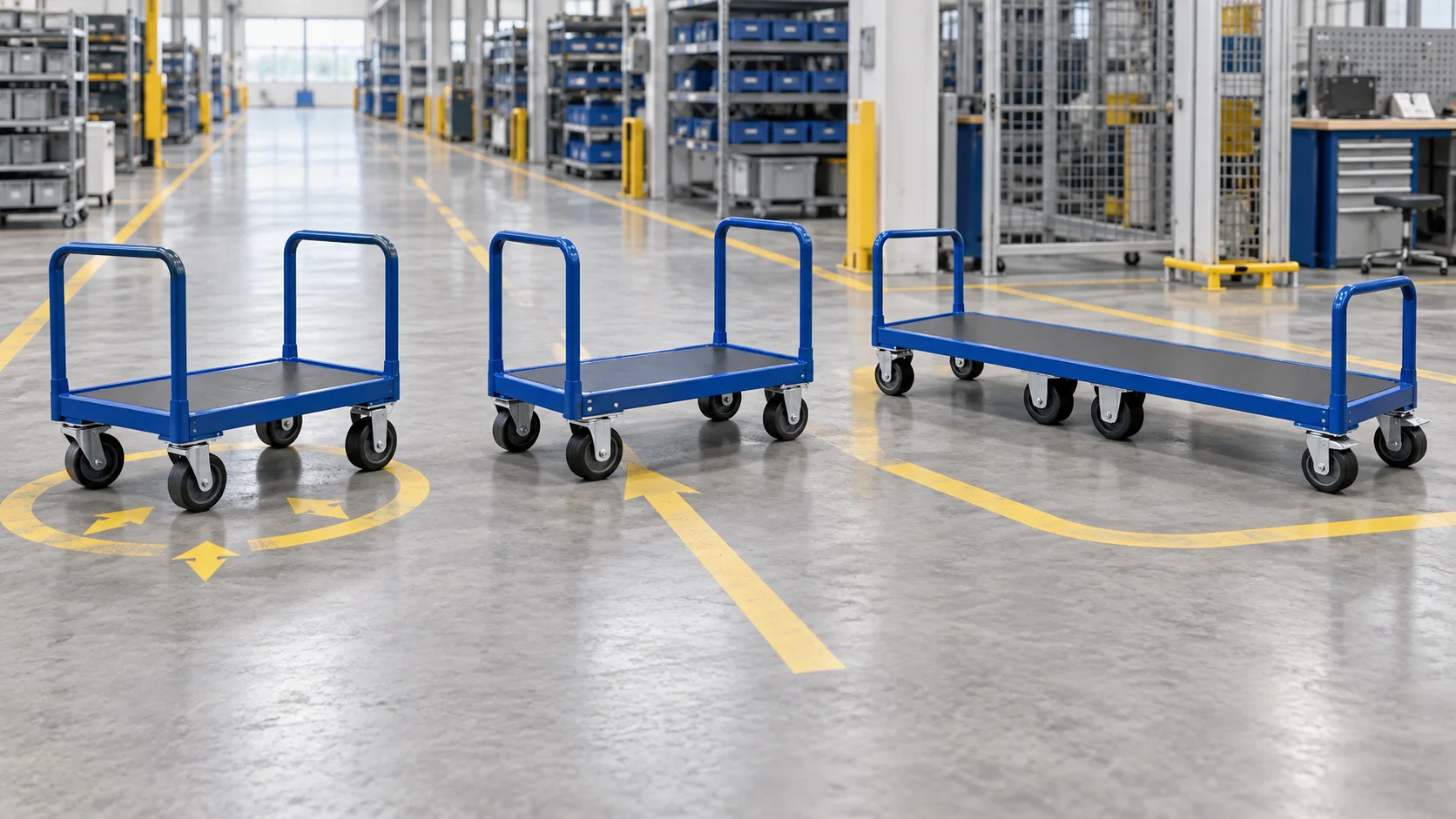
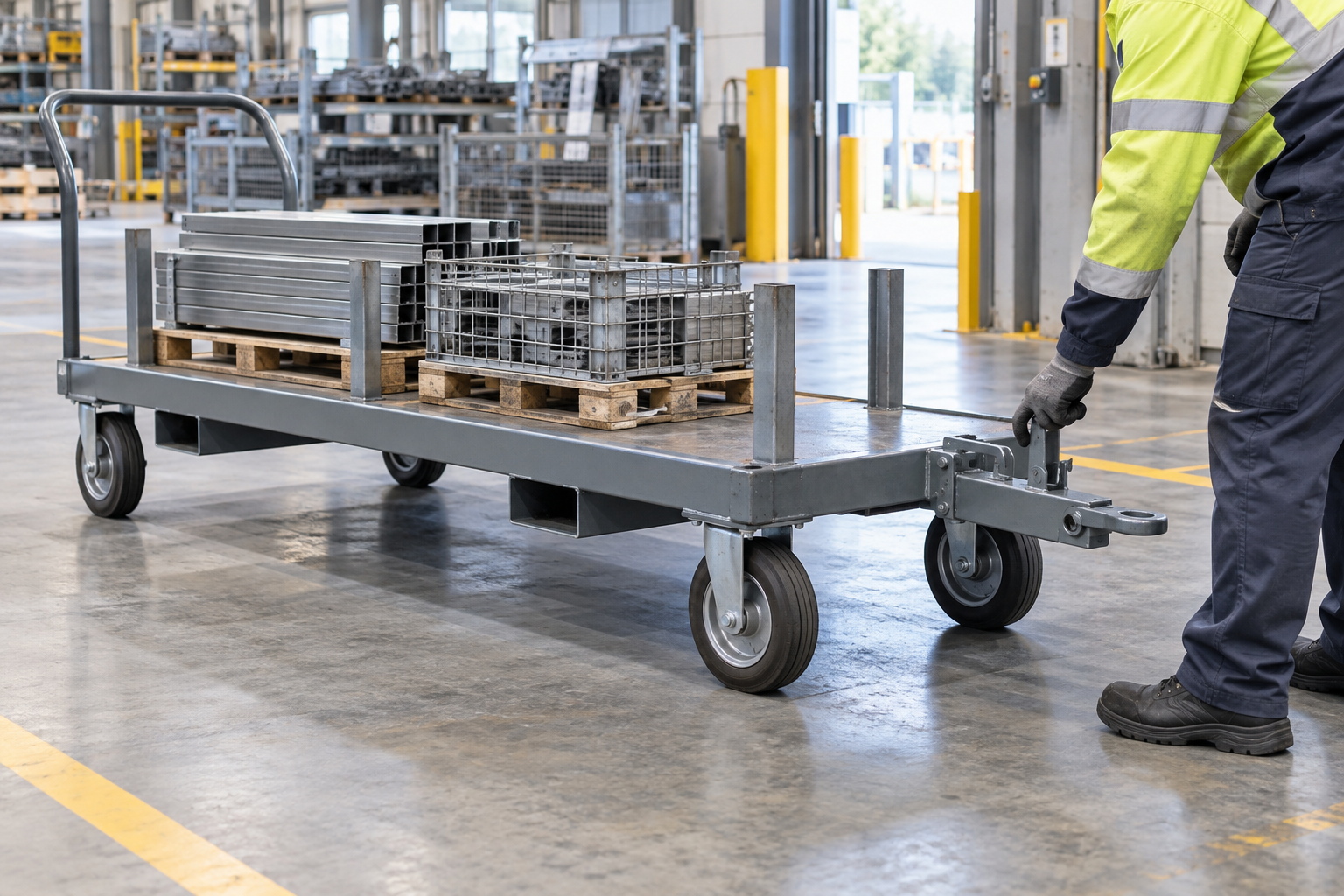
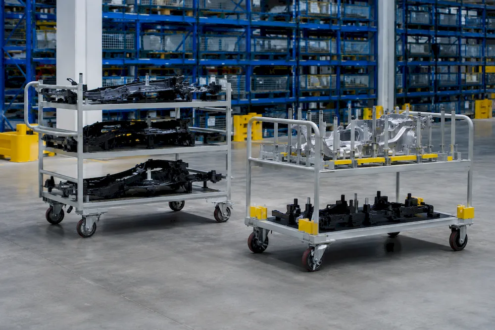
Design a Line-Side Trolley Dock That Stops, Holds and Presents Parts Repeatably

Design the dock as a matched interface: entry guides correct approach error, side datums establish lateral position, a structural rear stop sets depth, and a positive hold or floor lock prevents movement during the task. The operator-facing and replenishment sides determine the final parts presentation. Do not expect caster brakes alone to create a repeatable workstation datum. Send the trolley base and loaded centre of gravity, station layout, approach direction, required presentation, stop/hold/release task, floor condition and trial criteria to the supplier.
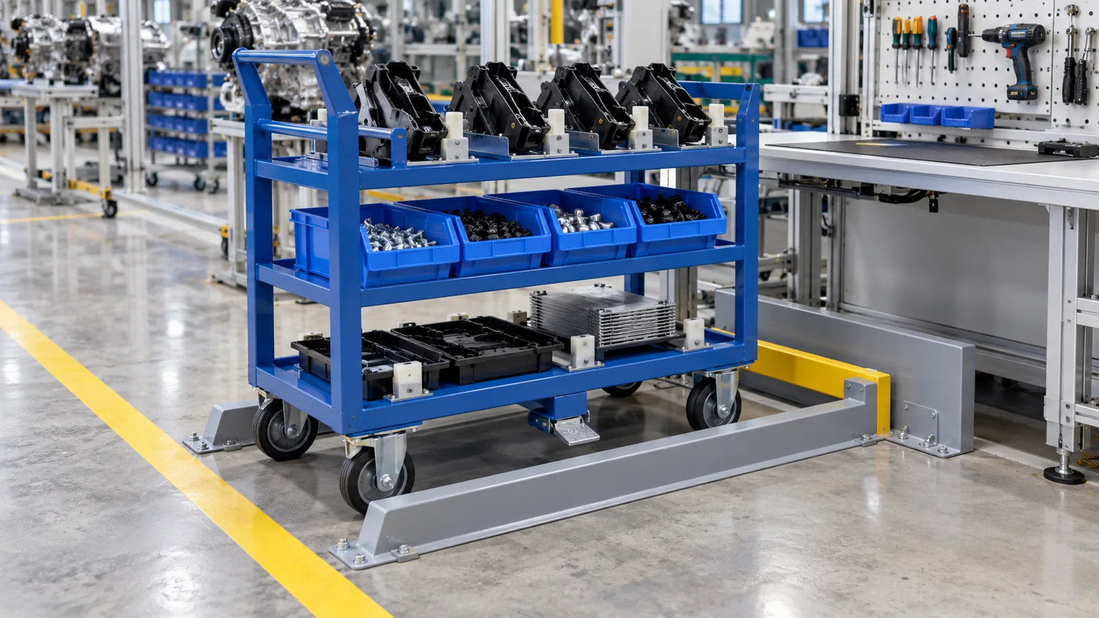
Design the line-side dock as a matched interface, not as a painted parking rectangle. Entry guides should correct realistic approach error; side datums establish lateral position; a structural stop fixes depth; and a positive hold, floor lock or suitable parking device prevents the trolley moving during the task. The required operator-facing position and replenishment side determine where those features belong. Send the supplier the trolley base and loaded centre of gravity, station layout, approach direction, floor condition, presentation datum, stop/hold/release sequence and a representative task trial.
The practical decision is the level of positioning and holding the workstation needs. SHT's stand-alone docking station combines a position aid, rear stop, automatic frame lock and release pedal. Its variable docking station adds adjustable guide and locking elements for different trolley dimensions. LTW's rapid-change workstation shows that the selected docking side belongs in the workstation concept. These examples do not define a HAOFU interface or guarantee repeatability; they show why guides, datums, stop, hold and release should be specified together.
Start with the required parts presentation
Before choosing a floor stop, define what must be repeatable at the station. It may be the front edge of a tote, the centreline of a tray, a height-adjusted picking shelf or clearance to a tool. Mark the operator-facing side, pick height, allowable lateral and fore-aft variation, and the side used for replenishment. This presentation datum becomes the output of the docking system.
Then work backward into the trolley base. Choose structural faces that can contact guides and the stop without bending a mesh panel, striking a caster or shifting the load. Keep foot space, handles, tow hardware and replenishment access clear. A trolley intended to dock from either end needs an explicit arrangement for each direction rather than an assumption that the frame is symmetrical.
| Dock function | Interface feature | Question to answer | RFQ input |
|---|---|---|---|
| Approach correction | Entry cone, funnel or angled guide faces. | How much lateral or angular error can the operator bring to the dock? | Approach path, aisle width and expected entry offset. |
| Lateral location | Side guides or defined frame datums. | Which trolley member can repeatably contact without interfering with wheels? | Base drawing, caster sweep and target presentation line. |
| Depth location | Structural rear or front stop. | Where can stopping force enter the frame without contacting cargo? | Stop direction, contact height and loaded mass/COG. |
| Parking hold | Frame latch, floor lock, wheel brake or other project device. | What movement must be prevented during picking or replenishment? | Floor/slope, task forces, release access and site requirement. |
| Release and departure | Pedal, lever, handle or controlled pull-out path. | Can the operator release and leave without reaching into a pinch zone? | Operator side, PPE, sequence and surrounding equipment. |
Controls fore-aft travel, while the operator still establishes lateral position and uses a separate parking device.
An entry cone and side datums correct approach error before a stop fixes depth and a brake or floor lock holds the trolley.
Guides, structural stop and a deliberate latch or lock create repeatable presentation with a defined release task.
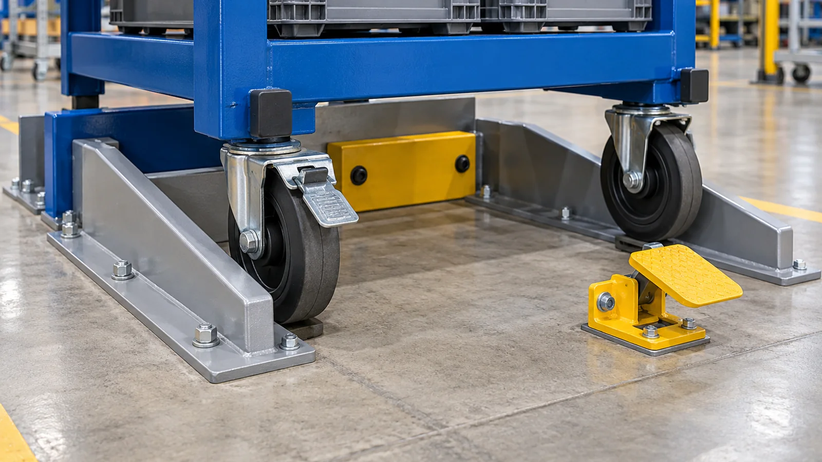
Use guides to correct approach before the stop
A stop cannot fix a trolley that reaches it at an angle. Place the widest part of the entry guide where the trolley can engage without catching a caster or creating a sharp pinch point. The guide should move the base onto the chosen side datums before it reaches the depth stop. Confirm the full caster swivel envelope and handle position through this motion.
The approach should match the real route. A perpendicular push from a clear aisle differs from a shallow-angle arrival beside a workstation. Floor joints, slopes and nearby columns can shift the entry path. Those conditions belong in the station layout even though they do not dictate a universal guide angle.
Make the stop a frame interface
The depth stop establishes the fore-aft presentation. It should contact a defined base-frame face that can accept the normal docking force and remain consistent across the trolley fleet. Avoid using a caster, sheet edge, latch or loaded part as the datum. Mark the contact height and direction on both the trolley and dock drawings so the two suppliers are reviewing the same interface.
Separate positioning from parking hold
Guides and a stop locate the trolley; they do not necessarily hold it during use. The holding method depends on the floor, slope, picking or replenishment forces and the site's safety assessment. A floor lock is one available component class—Jtec's floor-lock page illustrates a dedicated device that contacts the floor when the cart is parked—but its component dimensions and performance are not transferable to a custom trolley.
If a frame latch is used, define how it engages, how the operator confirms engagement and how it releases. If wheel brakes are used, check whether the operator can reach the correct wheels after docking and whether the brake action changes the trolley position. The design objective is a clear, accessible task—not the maximum number of devices.
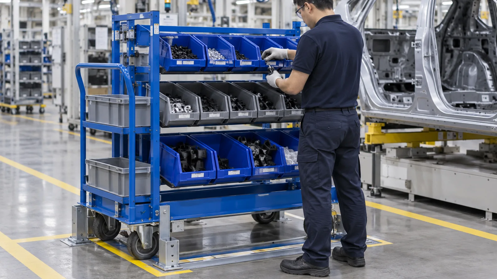
Protect the operator and replenishment sides
Once the trolley is docked, the pick face, empty-container return and replenishment path must remain usable. Do not place a release pedal where the operator stands or a guide rail where totes are withdrawn. If replenishment occurs from the opposite side, show whether the trolley remains held during that task. This guide addresses station docking; use the separate manual-push to tugger handoff guide when the same trolley also transfers into a tow route, and the caster-layout guide for wheel arrangement and steering behaviour.
- Fix the required parts presentationDefine the operator-facing side, pick height and allowable position tolerance.
- Map the real approachRecord travel side, angle, aisle, floor, slope, surrounding equipment and replenishment path.
- Select the entry correctionUse a suitable entry cone and guide faces to bring the trolley onto its datums.
- Define stop, hold and releaseGive each function a deliberate structural interface and an accessible operator task.
- Trial the complete station cycleApproach, dock, pick, replenish, release and leave with representative trolley and load conditions.
Five steps to prepare a line-side docking brief
- Fix the parts presentation. Mark the operator side, pick height, replenishment side and allowable position variation.
- Map the real approach. Show travel direction, entry angle, aisle, floor joints, slope and surrounding equipment.
- Select the correction and datum faces. Define the entry cone, side guides and trolley frame members that establish lateral position.
- Define stop, hold and release. Give the structural stop, parking device and operator release task their own clear interfaces.
- Trial the complete station cycle. Dock, hold, pick, replenish, release and depart with representative trolley, payload and floor conditions.
What to send for a custom material handling trolley quotation
Send the trolley and station layouts, payload mass and loaded centre-of-gravity information, target pick face and height, approach and departure sides, aisle and floor conditions, caster arrangement, structural guide/stop faces, parking method, release task, replenishment sequence, route constraints, quantity, destination and representative trial cycle. Review custom material handling trolleys, then send the trolley and workstation drawings for an engineering quotation.
Frequently Asked Questions
- What makes a material handling trolley dock repeatably?
- A complete dock uses entry guides to correct approach, side datums for lateral position, a structural stop for depth and a separate hold or lock to prevent movement during the task.
- Is a floor stop enough for a line-side trolley?
- A floor stop can set depth, but it does not necessarily correct lateral error or hold the trolley. Add only the guides, datums and parking device required by the workstation task.
- Can caster brakes be used as the docking datum?
- Caster brakes may help hold a trolley, but the repeatable station position should come from defined trolley-frame and dock datums. Check brake access and whether applying them shifts the trolley.
- Where should trolley docking guides contact?
- Use deliberate structural faces on the base frame that stay clear of caster swivel, cargo, handles and operator space. Do not use a mesh panel, wheel or loaded part as the position datum.
- Which side should a line-side trolley dock from?
- Choose the approach side from the aisle and station layout, then protect the operator-facing and replenishment sides. If more than one approach is required, define the interface for each direction.
- What should I send for a custom trolley docking quotation?
- Send trolley and station layouts, load and centre of gravity, presentation datum, approach path, floor and slope, caster arrangement, guide/stop/hold/release sequence, replenishment task, quantity, destination and trial criteria.