How to Position Stillage Supports for Long and Irregular Parts

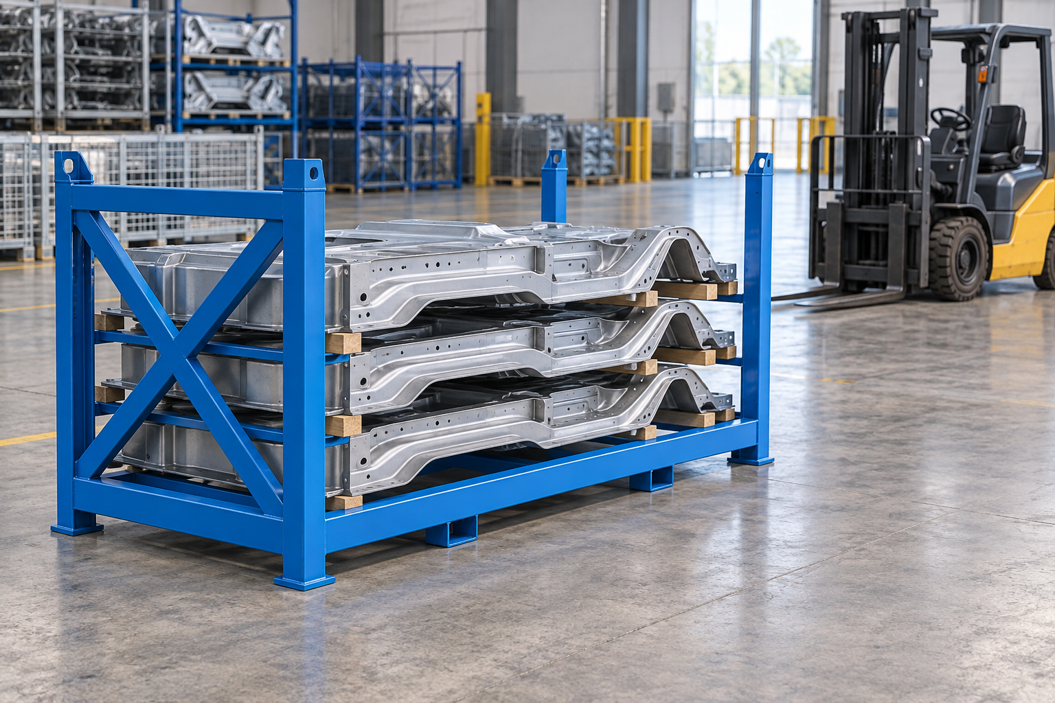
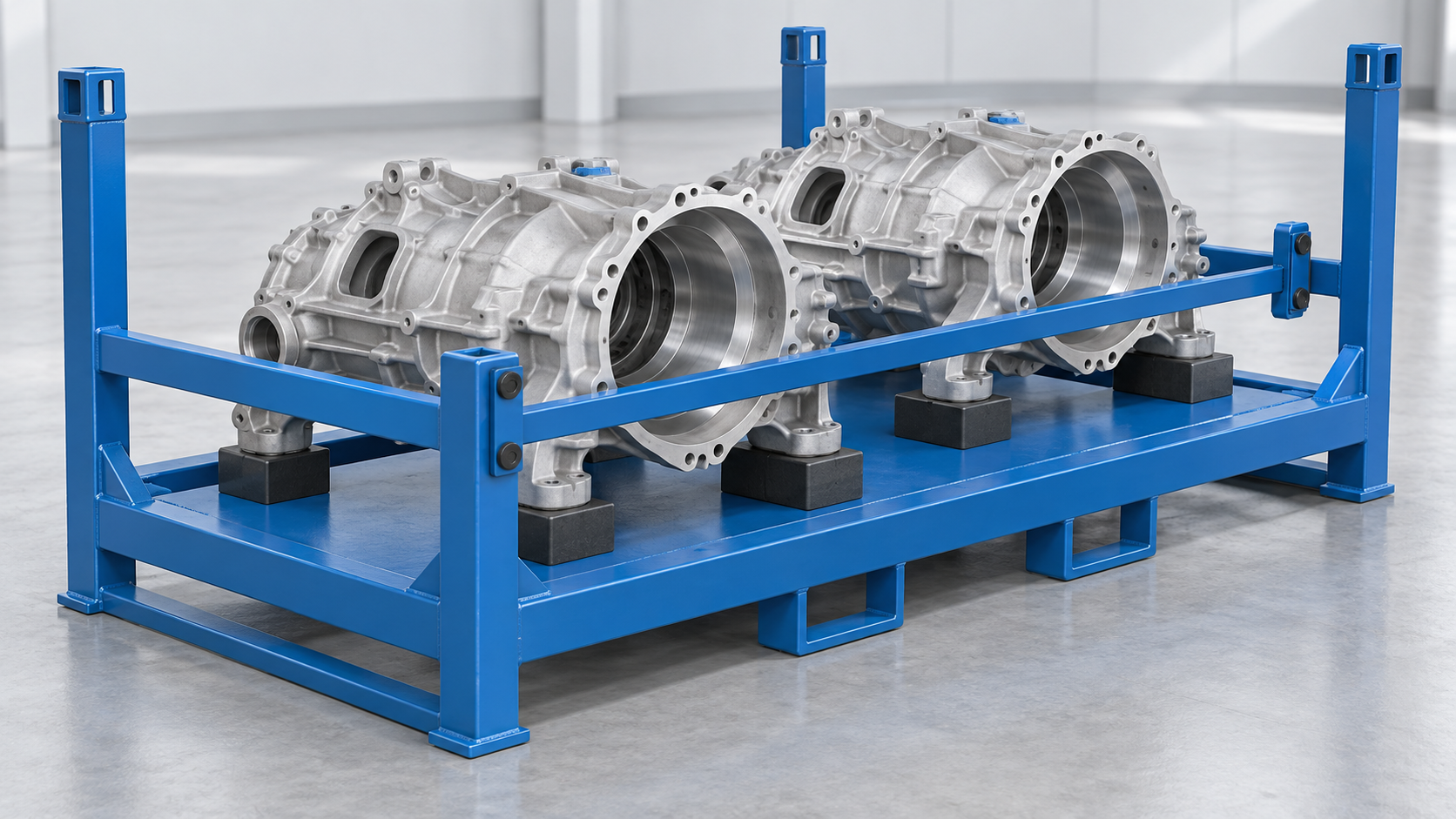
Do not space stillage supports from the outside length alone. Mark the component's approved and restricted contact zones, end overhang, centre of gravity, sensitive sections and pickup points. Then trace the long-side, end-side or top-loading motion and place discrete cradles where the part may bear without blocking hands, slings, forks or lift-assist tooling. Treat restraints separately from supports, and have the project structure reviewed for the actual load case. Send CAD, mass/COG, contact-zone and loading-path data to the stillage supplier.
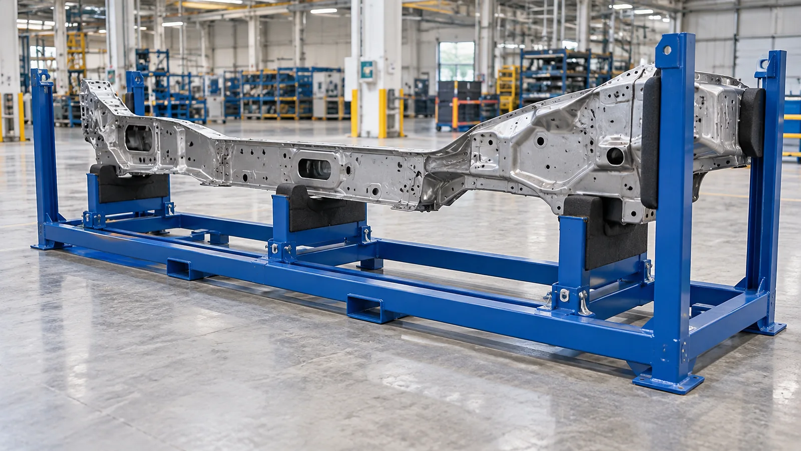
Position stillage supports from approved part-contact zones and the real loading path, not from equal spacing along the outside length. Mark where the component may bear, where contact is restricted, how much end overhang exists, and where hands, slings, forks or lift-assist tooling need to pass. Then choose two defined supports, several discrete cradles or a broader profile nest so the part can approach, seat, be restrained and leave without unintended contact. Provide the supplier with part CAD, mass and centre of gravity, permitted contact areas, loading direction and the intended handling cycle for the project structural review.
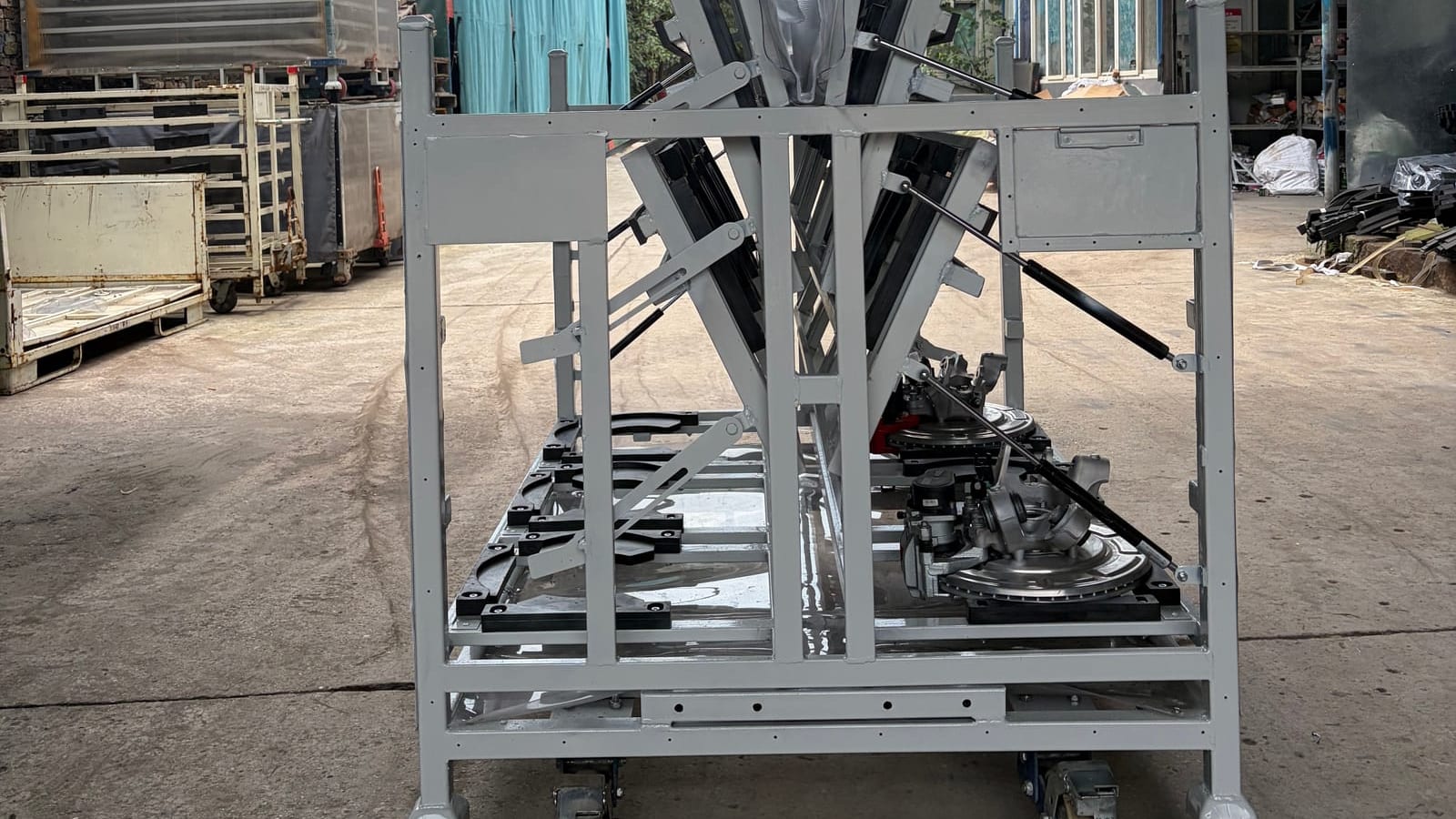
Custom stillage suppliers consistently connect support layout with the item being handled. JS Burgess describes designs for long products with support along their length, while Specialised Stainless notes that support spacing can be adapted to the product and handling equipment. Conquip's formwork stillage is a useful example of long-item access and retention as a combined product task. Their dimensions and capacities are not HAOFU specifications; the transferable lesson is that the supplier needs the actual component and loading sequence.
Map approved contact before choosing support count
Begin with the component, not the steel frame. On the part CAD or drawing, highlight broad bearing areas, local bosses or pads that may contact the stillage. Mark finished surfaces, ports, thin edges, flexible covers and other restricted zones. Add the centre of gravity and the range of part revisions or variants expected in the same carrier.
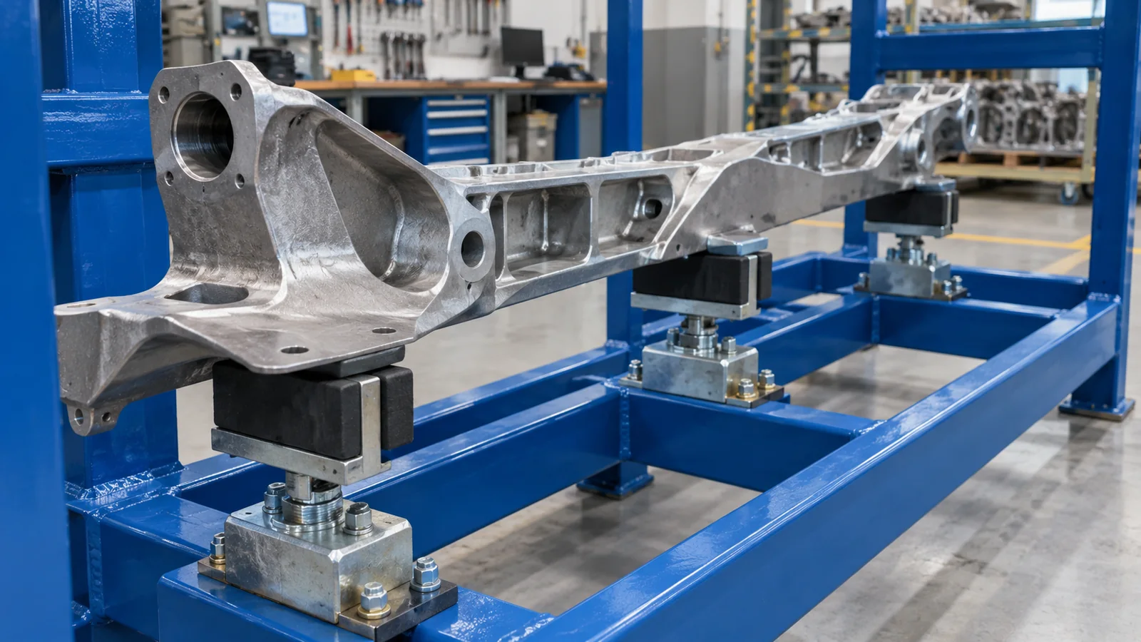
This map may immediately rule out equal spacing. The geometric midpoint might be a no-contact surface, while two stronger bearing lands sit closer to one end. An irregular component may need different cradle heights or shaped interfaces to reach approved zones. If the part supplier specifies lifting or support points, include those instructions rather than recreating them from photographs.
| Part condition | Support approach to examine | Loading-path effect | RFQ evidence |
|---|---|---|---|
| Two clear bearing zones with open centre | Two defined support stations. | Centre stays available for a sling, fork or lift-assist tool. | Contact zones, mass/COG and end overhang. |
| Several approved lands on irregular geometry | Multiple discrete cradles at controlled heights. | Tooling moves through planned gaps between stations. | Section CAD, datum scheme and insertion path. |
| Broad approved underside profile | Continuous or long profile nest. | Part normally needs a clear vertical lift-off direction. | Full underside surface and removal direction. |
| Sensitive ends or attachments | Move bearing inward to approved structure and control overhang. | End access remains clear; handling avoids attachments. | Restricted zones and maximum permitted overhang. |
| Multiple variants share one stillage | Fixed common contacts plus identified replaceable or adjustable features. | Changeover hardware cannot block the loading route. | Overlay CAD, variant list and changeover sequence. |
Works when two approved bearing zones are clear and the part can bridge them in the project load case. Review end overhang and lift access.
Uses several approved contact stations to follow irregular geometry while leaving deliberate gaps for loading or extraction tools.
Fits a broad approved underside profile when repeatable positioning matters. Preserve drainage, cleaning and vertical release clearance.
Treat end overhang as an engineering input
End overhang is the distance from the outer support to the end of the component. It affects the exposed envelope, the way the part enters the stillage and the project load case. It also changes where an operator or lifting device can grip the part. Show both ends because an asymmetric component may have different conditions even when the stillage looks centred.
Do not infer an allowable overhang from a competitor rack or from a previous part. Provide the part's material and section information, mass distribution, centre of gravity, approved support areas and handling environment so the relevant parties can review the project. The article helps define supplier inputs; it does not replace the part owner's deformation criteria or the stillage structural calculation.
Coordinate support stations with loading direction
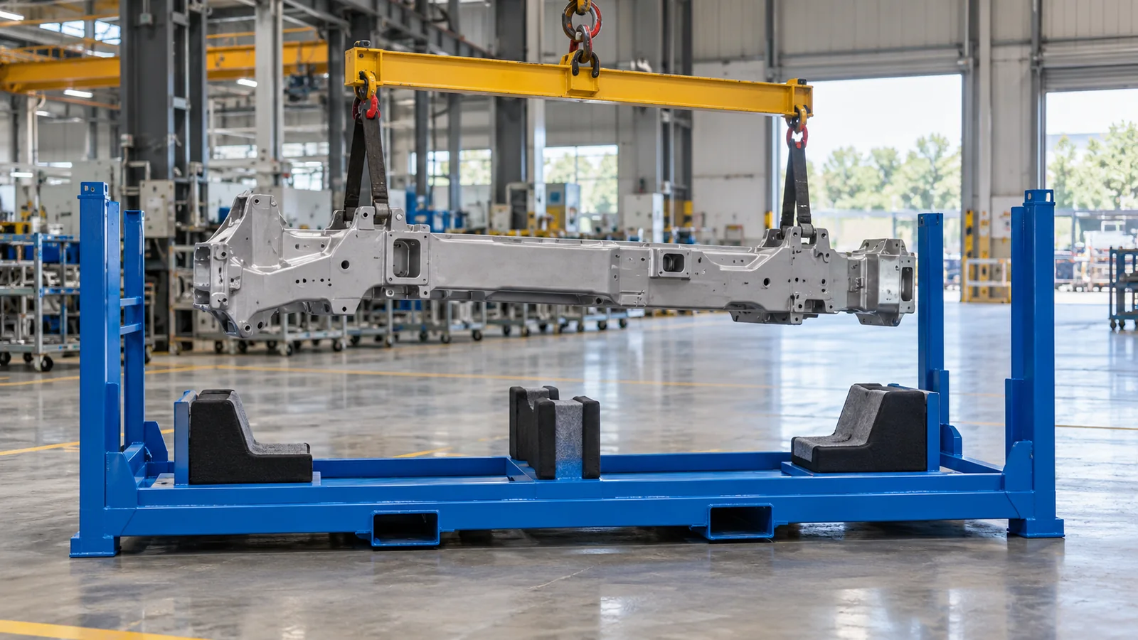
A support can be correctly located for bearing and still block the actual loading motion. For long-side loading, trace the component and the handling device through the open face before it reaches every cradle. For end loading, check whether each support allows the part to pass or whether the part must be lowered after insertion. For top loading, reserve vertical access for slings, hooks, lift beams or end effectors and confirm their release path.
This decision is narrower than choosing the stillage's general loading face. The loading-face and cross-brace guide helps decide which frame side stays open; this guide places the bearing stations inside that chosen opening. Both drawings should use the same part motion and handling-tool envelope.
Keep support and restraint as separate functions
Supports establish where gravity loads enter the stillage. Restraints control movement away from those seats during handling and transport. A side stop, strap, clamp or retainer should not become an unintended bearing point because the part shifts before the approved cradles engage. Give each feature a clear function on the drawing and show its open, closed and stored states.
For a machined or sensitive component, use the support-and-restraint guide for machined castings to develop contact restrictions. Then bring those approved contact inputs back to the stillage layout. The final contact material, attachment and replacement detail depend on the surface and operating environment.
Connect the supports to the stillage base
Every cradle transfers load into cross-members and the base frame. Once the contact stations are chosen, align the supporting steelwork with them while preserving fork entry, runners, feet and stacking interfaces. Avoid shifting a cradle simply to match an arbitrary frame grid if that move creates poor part contact; resolve the part and frame drawings together.
The UK's workplace-transport loading guidance emphasizes suitable loading methods, stability and clear responsibilities. Apply the specific site rules and engineering review to the intended stillage, payload and stack; no generic support spacing proves capacity.
- Mark approved and restricted contact zonesUse the part drawing and supplier instructions to identify where each part may bear.
- Trace loading and unloading motionInclude the component, hands, slings, forks or lift-assist tooling through approach and removal.
- Place candidate support stationsCoordinate bearing zones, end overhang, centre of gravity and clear pickup spaces.
- Add restraint as a separate functionLocate side stops, straps or retainers without turning them into unintended load-bearing points.
- Trial the worst part and orientationLoad, secure, transport, release and unload a representative sample before production.
Five steps to prepare a long-part stillage layout
- Mark approved and restricted contact zones. Use current part CAD and supplier instructions, including variants and sensitive surfaces.
- Trace the complete loading motion. Show long-side, end-side or top approach, seating, release and empty-tool withdrawal.
- Place candidate support stations. Coordinate bearing zones, end overhang, centre of gravity and open pickup spaces.
- Add restraint without changing the bearing scheme. Give stops, straps and retainers their own accessible positions and stored states.
- Trial the worst representative part. Load, secure, handle, release and unload with production-intent equipment before final production.
What to send for a custom stillage quote
Send part CAD and sections, mass and centre of gravity, approved and restricted contact zones, permissible orientation, end-overhang constraints, loading/unloading direction, handling-tool envelope, quantity per stillage, fork interface, stacking and route conditions, part variants, quantity, destination and proposed acceptance trial. Review custom stillage racks from a China-based manufacturer, then send the part and handling drawings for an engineering quotation. Those inputs let the supplier develop support stations around the component instead of applying a generic equal pitch.
Frequently Asked Questions
- Should supports for a long part be equally spaced?
- Not by default. Position supports from approved bearing zones, part geometry, centre of gravity, end overhang and the loading path. Equal spacing may place a support on a sensitive or weak surface.
- Are two support stations enough for a long component?
- Two may be suitable when the approved contact zones and project load case support that arrangement and the centre remains useful for handling. The part owner and stillage supplier need the actual geometry, mass distribution and acceptance criteria.
- How should end overhang be specified?
- Show the distance from each outer support to the end of the part, plus any sensitive attachments, pickup points and route clearances. Review both ends because an irregular component may be asymmetric.
- What are approved contact zones?
- They are surfaces or local areas where the part may bear on the stillage. They should come from current part drawings or supplier instructions and exclude finished, thin, flexible or otherwise restricted features.
- How does loading direction affect support placement?
- Supports must carry the part after seating without blocking its approach, lowering, release or withdrawal. Trace the part and the complete handling tool for long-side, end-side or top loading.
- What should I send for a custom long-part stillage quote?
- Send part CAD and sections, mass and centre of gravity, approved and restricted contacts, loading direction, handling-tool envelope, end-overhang constraints, fork and stacking conditions, quantity and the proposed acceptance trial.