Transport Racks for Machined Castings: Where Should the Part Rest?

For a machined casting transport rack, mark three zones on the current part drawing: surfaces allowed to carry its weight, surfaces allowed to limit side movement, and machined or sealing faces that must remain clear. Give the rack supplier the part orientation, mass, handling route and permitted contact materials, then check the proposed supports and stops with a representative part before release.
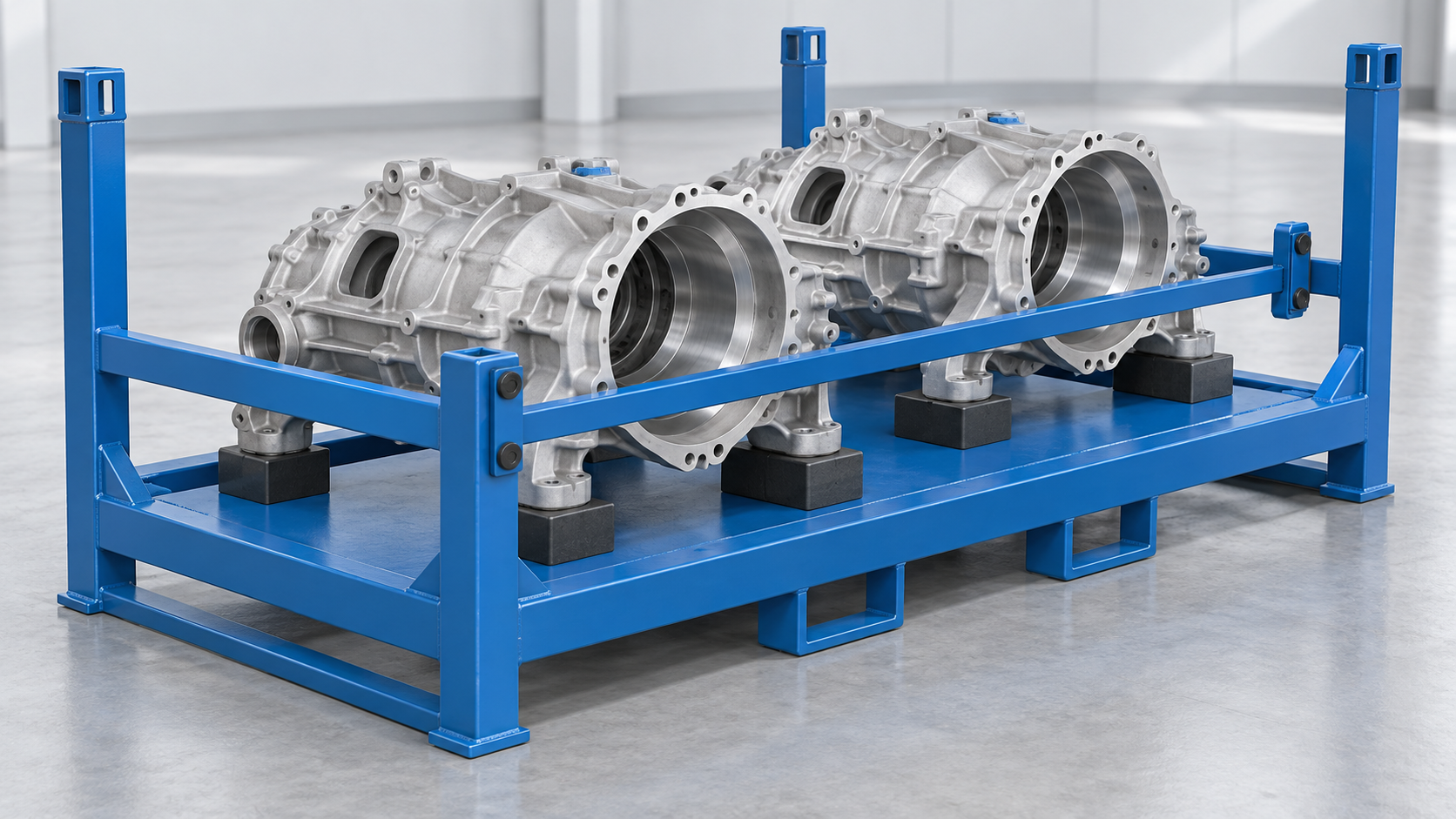
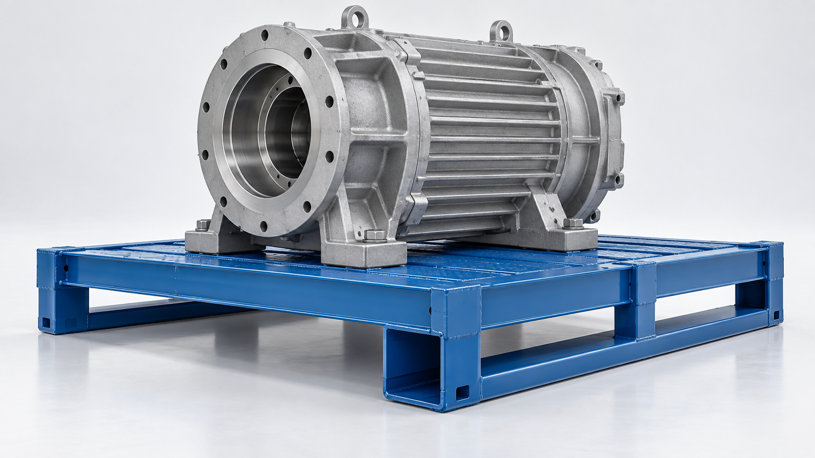
A machined casting transport rack should support the part on buyer-approved bearing zones, restrain sideways movement at separately identified points, and leave critical machined or sealing faces clear. Start with the casting drawing and its real travel orientation: mark what may carry weight, what may touch only as a stop, and what must never touch the rack. Then give the supplier the part mass, centre-of-gravity information, quantity per rack, handling route and loading method. A drawing of a generic steel frame cannot answer those questions for a particular housing.
This distinction matters for engine, gearbox and other machined housings because an accessible cast rib may be suitable for one job but not another. The buyer's part engineer or quality team must identify permissible contacts; a supplier can then turn those inputs into an automotive rack proposal. Morrison's automotive-rack overview likewise treats product geometry, dunnage and retention as connected choices, while the exact contact decision remains part-specific.
Support, restraint and clearance are different jobs
A bearing pad carries the part's vertical load. A side stop limits travel when the rack accelerates, turns or is handled. A clearance zone protects a feature such as a finished bore, mating face, threaded opening or seal land. Do not turn a side stop into an unintended bearing pad merely because it is close to the casting. Equally, leaving every face untouched is not a design: the part still needs a stable load path and controlled movement.
| Drawing mark | Buyer should specify | Supplier should show |
|---|---|---|
| Bearing | Permitted cast boss, rib or pad location; load direction and allowable contact area. | Support position, pad shape, attachment and how the load reaches the rack frame. |
| Restraint | Permitted lateral-contact area and movement or clearance requirement. | Stop position, access for placement/removal and how an off-nominal part is handled. |
| No contact | Machined, sealing, cosmetic or inspection-critical faces and relevant tolerance range. | Clearance in the proposed orientation, including variation and expected part motion. |
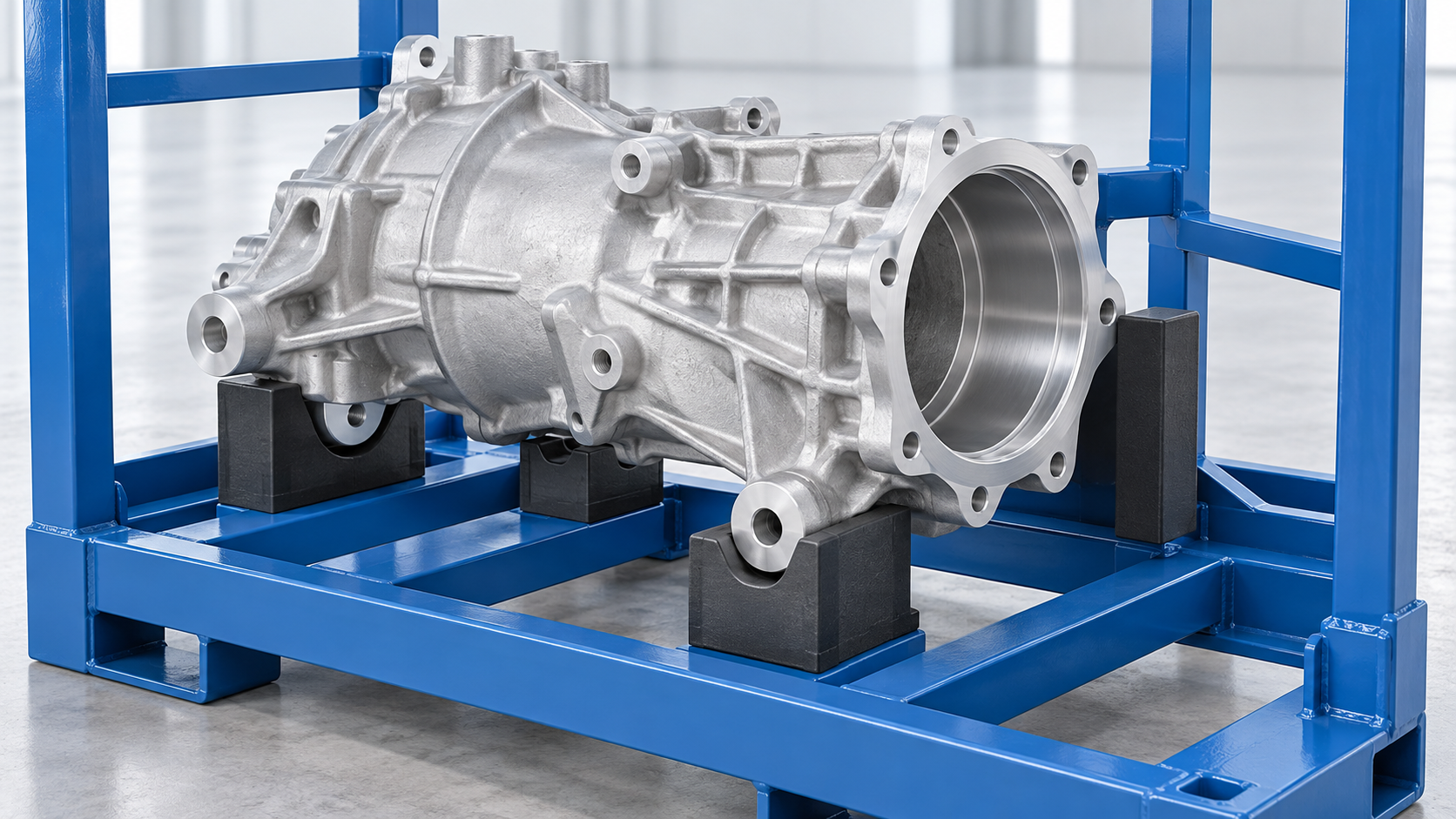
Choose contact zones from the actual part, not its outline
Ask engineering to circle robust features that can bear the part in the chosen orientation, then distinguish them from surfaces that can tolerate a light lateral stop. Include the as-cast and machined revisions if they differ. Where a part family shares a rack, mark the worst-case geometry and each variant's contact restrictions; do not assume one housing drawing covers every revision. A photo can explain access, but the controlled drawing or sample is needed to settle the interfaces.
Nefab's rack-dunnage examples show that interface formats vary with the part. Material selection is a later question than the allowed contact map. Our separate dunnage approval guide covers material and sample sign-off; this guide owns the earlier support-versus-restraint decision.
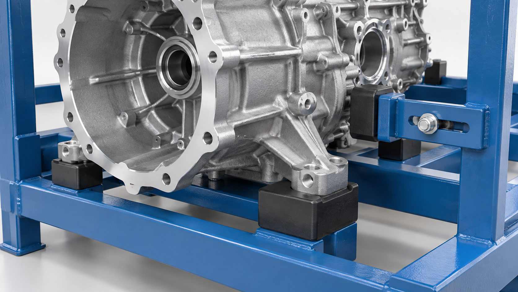
Make the loading route part of the drawing
A support may look sensible in a static model yet block the operator's hand, a hoist sling or a lifting attachment. Describe whether the part is lowered vertically, presented from the side, rotated into place or removed at line side. Show where the part is held during placement and where the operator must be able to see or reach. Southern Perfection's transit-damage discussion identifies part movement as a packaging consideration; the useful next step for a buyer is to show the actual movement and contact plan, rather than specify a generic “protective pad.”
Five steps to brief a rack supplier
- Send the current part definition. Include the released drawing or a representative sample, revision, part mass and orientation.
- Mark the three contact classes. Identify permitted weight-bearing, side-restraint and no-contact zones; note part-family variation.
- Describe the route. State quantity per rack, loading/unloading motion, forklift or other handling, storage and return conditions.
- Review the proposed layout. Ask the supplier to show pads, stops, frame load path and access on the drawing, with unresolved contacts called out.
- Trial the actual part. Check fit, removal, clearance and the buyer's acceptance points before releasing the rack configuration.
For adjacent decisions, the engine-rack RFQ guide expands the weight/COG and handling input, while the prototype-to-production guide explains how to document a representative trial. A supplier-specific packaging guide such as Daimler Truck's can add programme requirements, but it does not replace your own part-contact approval.
Get a rack proposal around your casting
HAOFU develops custom automotive parts racks in China for defined components and handling routes. Send the marked part drawing or sample, permitted contact map, mass, rack quantity, loading motion and destination through the automotive rack engineering RFQ. Tell us which contacts are already approved and which need your team's decision; we can respond with a proposed layout for review.
Frequently Asked Questions
- Where should a machined casting rest in a transport rack?
- It should rest on bearing zones approved for that exact part and orientation. Mark the permitted cast bosses, ribs or pads on the controlled drawing and review the rack support layout with the part engineer.
- Can a side stop also carry the casting's weight?
- Only if the part and rack design explicitly allow it. Treat vertical bearing and lateral restraint as separate requirements so an unintended contact does not become the load path.
- Which surfaces should stay clear of the rack?
- Mark machined bores, mating or sealing faces, cosmetic faces and any other buyer-defined no-contact areas. The required clearance must account for the chosen part orientation and variation.
- What should I send to request a casting rack design?
- Send the current part drawing or sample, mass and centre-of-gravity information, approved bearing and restraint zones, no-contact faces, parts per rack, loading motion, handling route and acceptance requirements.
- Does one rack layout work for every casting revision?
- Not automatically. Check each revision or part-family variant against the same support, restraint, clearance and handling map before treating it as compatible.