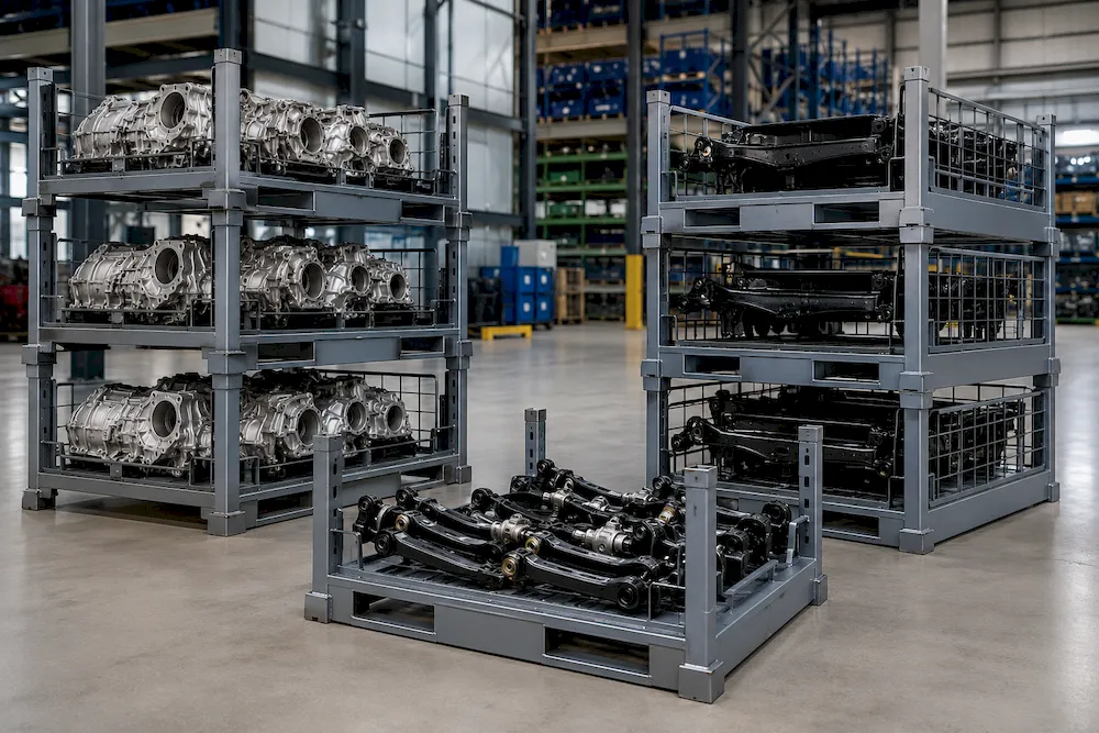
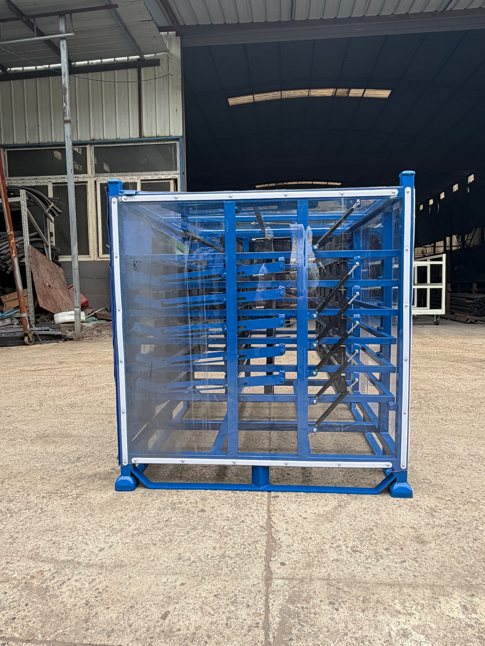
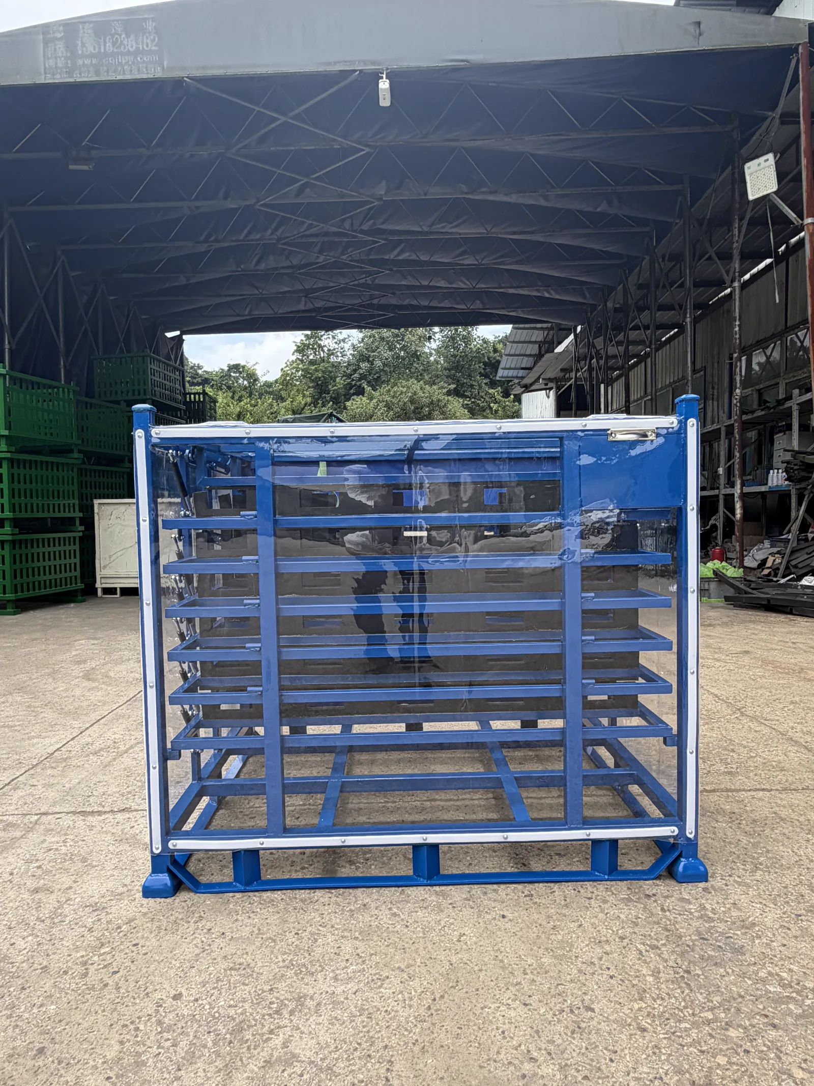
Choose a Stillage Loading Face Before You Place the Bracing

Choose a stillage loading face by tracing how the first and last parts enter and leave. Long-side access suits a lateral path along the part length; end-side access can suit an end-first motion or narrow work-cell approach; top loading needs a clear vertical lift envelope. Once that route is chosen, place braces, panels, removable sides and fork-entry faces so they do not block it. Send the supplier part CAD, loading motion, fixture/grip, handling equipment and loaded/empty views for a drawing review.
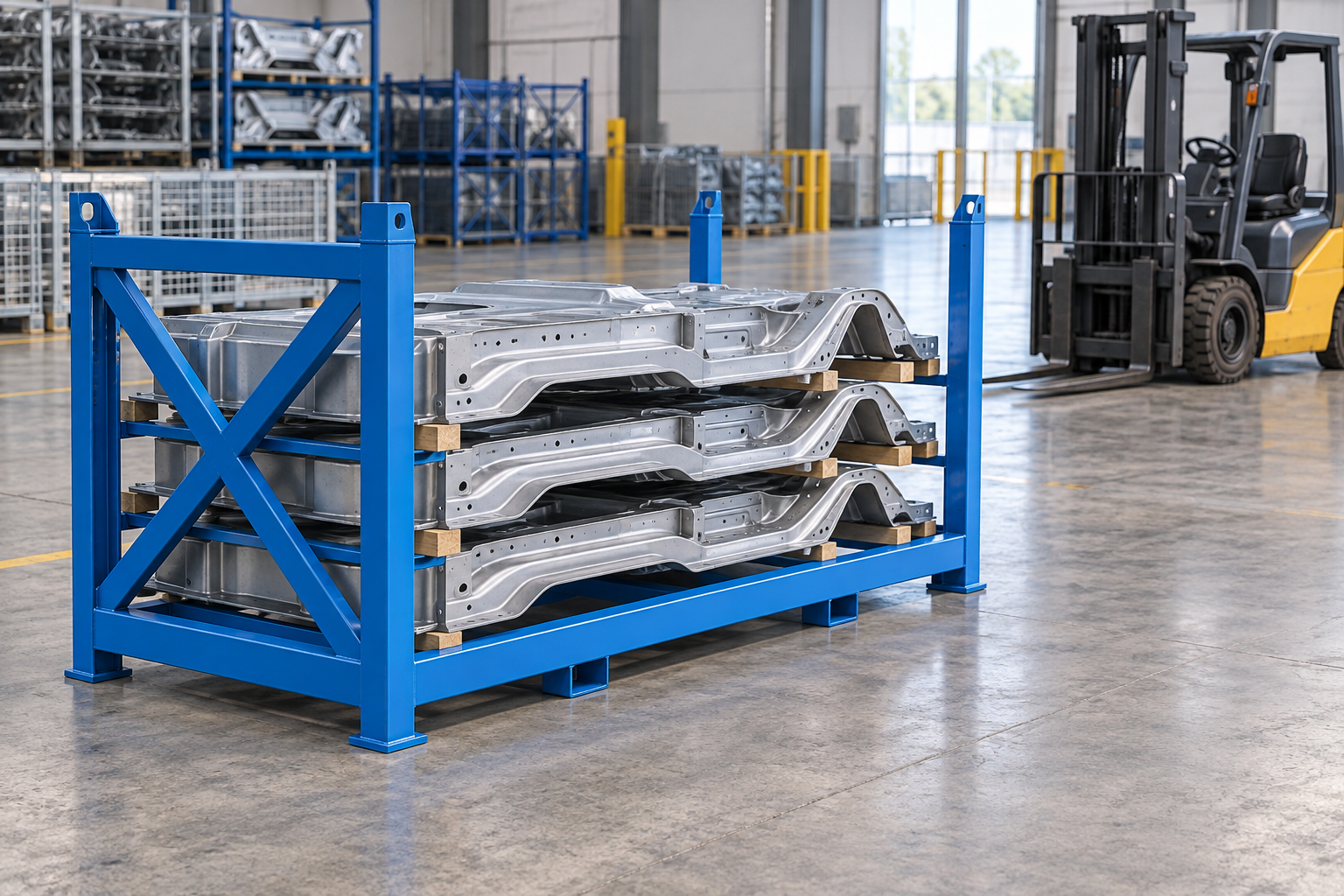
Choose a stillage loading face by tracing the real part movement before you fix the cross-braces, panels or removable sides. A long-side opening can suit a part that slides or is lifted laterally along its length; an end opening can suit an end-first approach; top loading needs a clear vertical path for the part and its lifting method. Draw the first and last part paths, then keep those paths clear while the remaining faces carry the required frame members. The final structure and handling arrangement must be reviewed against the approved part, route and project requirements.
This turns a vague request for an “open side” into a purchase decision. Lowe's bespoke-stillage overview correctly centers access height, post and divider positions on how the load sits in use. Rack & Shelf similarly shows that removable side members and fork tunnels are separate layout choices. These are useful industry examples, not HAOFU specifications or performance evidence.
Trace the part path before choosing the open face
| Loading face | Works best when | Check before approving |
|---|---|---|
| Long side | The part enters or leaves sideways along a long profile. | Part sweep, operator/fixture clearance, side rails and where diagonal bracing can sit. |
| Short end | The part is presented end first or the workstation only has an end approach. | Entry angle, turning room, end-frame members and the final-part exit. |
| Top | A crane, hoist or vertical fixture lowers and lifts the part. | Overhead path, upper beams, slings/fixture and any stacked view. |
Keep a lateral path along the part length and brace the non-access faces.
Fits an end-first move or narrow approach; draw the full exit sweep.
Needs vertical clearance for the part and lifting method before upper members are placed.
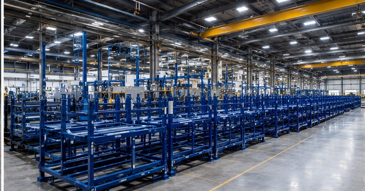
Keep the access path and frame layout on one drawing
Mark the part silhouette in its loaded position and add its full entry and exit envelope. Include the grip point, lifting fixture or tool, and show the last-part condition after neighboring positions are empty. Then place the end frame, diagonal brace, removable panel, divider and fork entry in that same view. A strong-looking brace is not useful if it crosses the only route that lets the part leave the stillage. A removable component is not useful if there is no place to hold it or no clearance to remove it.
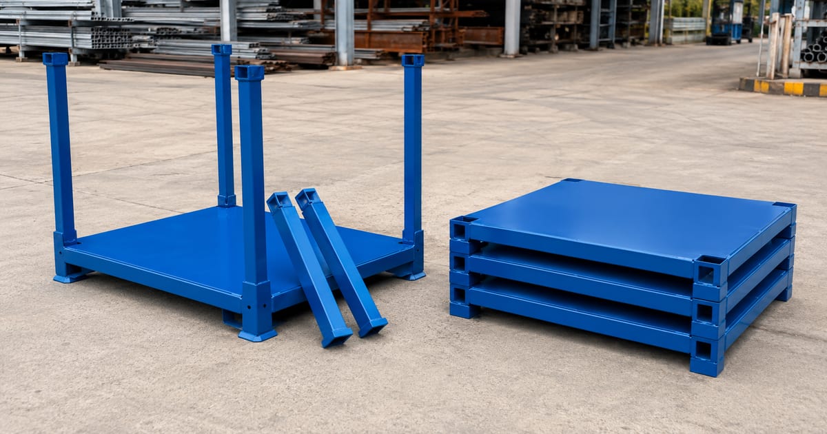
Include fork direction without letting it replace the part decision
Fork entry determines how the carrier is picked up and set down; it does not by itself decide where the part should enter. Review both on the layout: fork approach, mast and tine clearance, the side presented at the station, any rack-beam or vehicle orientation, and how the loaded and empty carrier is stacked. Range Storage's current stillage handling article is a useful reminder that fork pockets, gates and access are connected in a custom layout. It does not validate a configuration for a different truck, part or route.
- Trace entry and exitDraw the first and last part path with the actual grip or fixture.
- Choose the loading faceCompare long-side, end-side and top access.
- Place frame membersSet braces, panels and removable components away from the selected path.
- Check handling viewsReview fork, lifting and stack positions with the intended loaded state.
Five steps to turn the loading motion into a frame layout
- Trace the part movement. Draw the first and last part path with its grip, fixture or lifting method.
- Choose the loading face. Compare long-side, end-side and top access against the workstation and part movement.
- Place the frame members. Locate braces, panels, posts and removable components outside the selected part path.
- Review handling directions. Add fork or crane approach, set-down orientation and loaded or empty stack views to the layout.
- Trial the proposed movement. Check the representative part through the chosen entry and exit path before releasing the final layout.
What to send for a custom stillage quotation
Send released part CAD, revision and photos or sample information; part mass and centre-of-gravity information; permitted contact and no-contact zones; quantity per carrier; first/last loading sequence; operator grip or lifting fixture; long/end/top approach sketch; forklift or crane details; loaded/empty stack views; route constraints; quantity and acceptance task. Compare related decisions in the stillage selection guide, forklift-entry guide and removable-post guide.
For a project-specific custom stillage rack, send the full loading and handling brief through the stillage RFQ form. The commercial team can review a supplier-ready drawing package; final dimensions, frame design and handling acceptance remain project-specific.
Frequently Asked Questions
- Which side of a stillage should be open?
- Open the face that matches the actual part entry and exit path. Compare long-side, end-side and top loading with the first and last part, operator grip or fixture, and workstation approach.
- Can a cross brace sit on the loading side?
- Only if it stays outside the full part and handling envelope. Draw the part path, grip or lifting fixture and any rotation before fixing a brace or side member on that face.
- Does forklift entry decide the stillage loading face?
- No. Fork entry decides how the carrier is picked up and set down; part access decides where the component enters or leaves. Review both directions on the same layout.
- When is a removable side useful on a stillage?
- It is useful when removing it creates a workable part path and there is clearance and a defined place to handle that component. Test the proposed action with the actual loaded state.
- What does a stillage loading-face RFQ need?
- Send current CAD or a sample, revision, mass and centre-of-gravity information, contact restrictions, parts per carrier, first/last movement, grip or fixture, access sketch, fork or crane details, stack views, route and quantity.