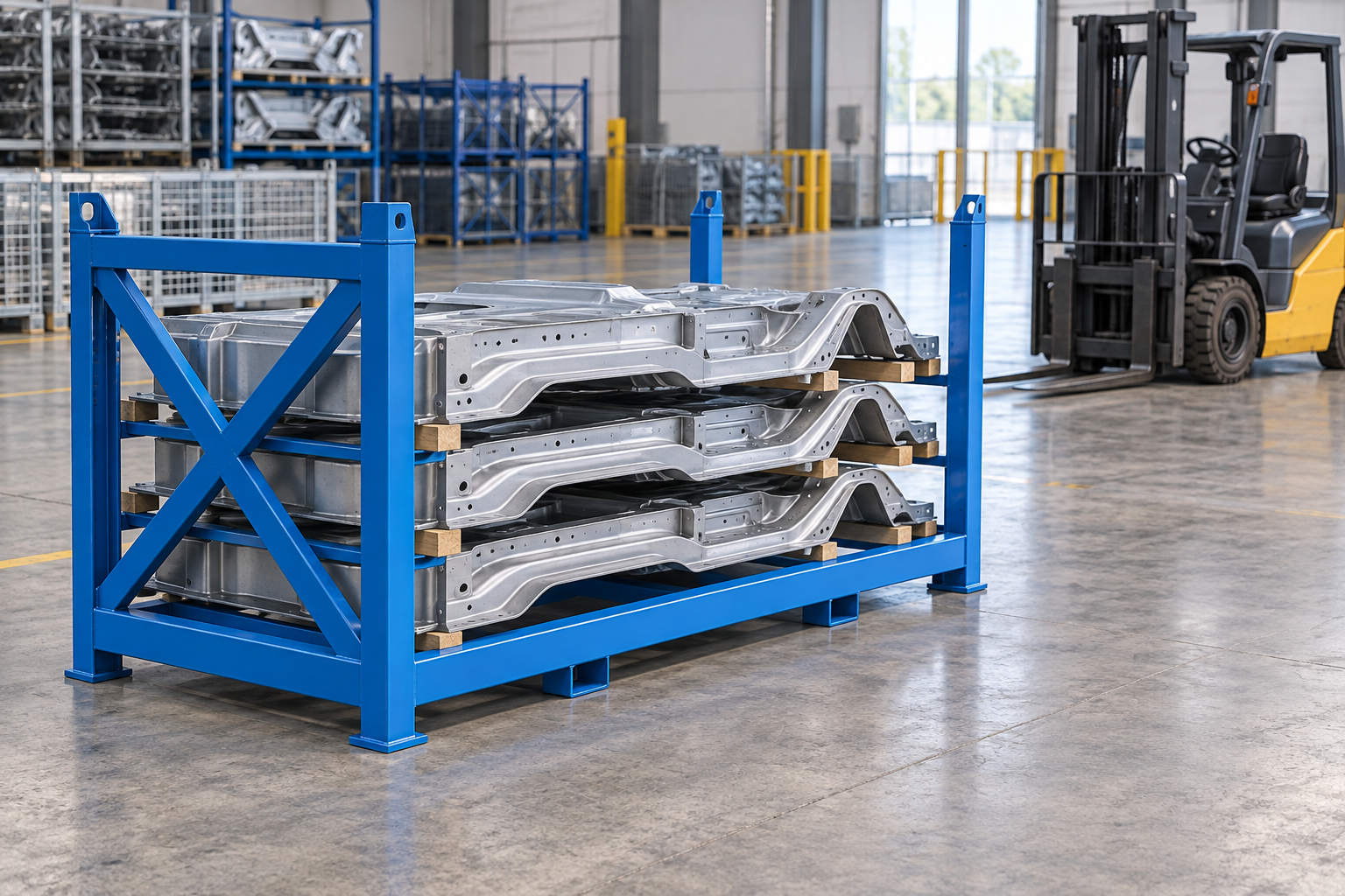
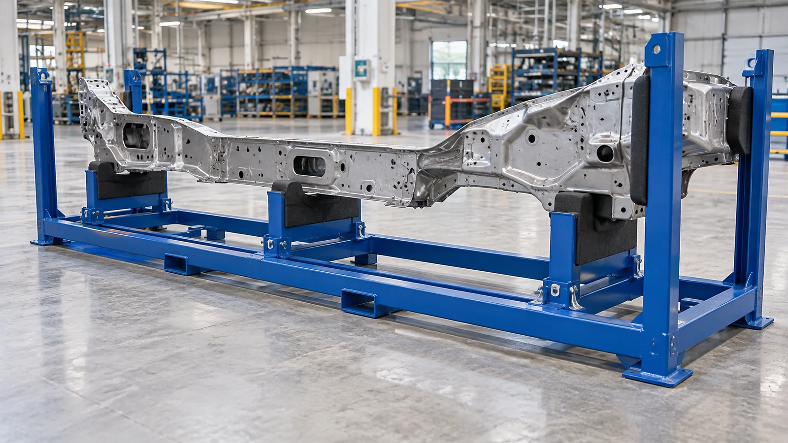
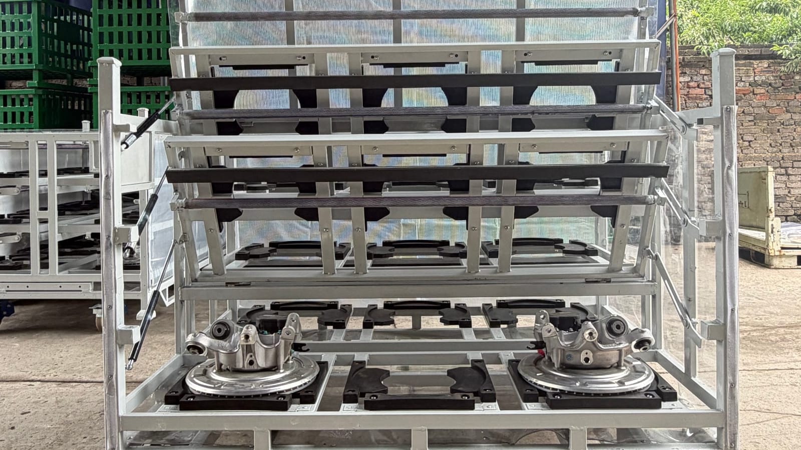
Single-Layer or Multi-Tier Stillage: Choose Usable Part Positions

Use one layer when the part set needs a common open approach. Compare fixed tiers when every position remains accessible with adjacent levels occupied. Include release, handling and storage for any moving level. Quote the positions that can actually be used; internal shelves and external whole-rack stacking are separate decisions.
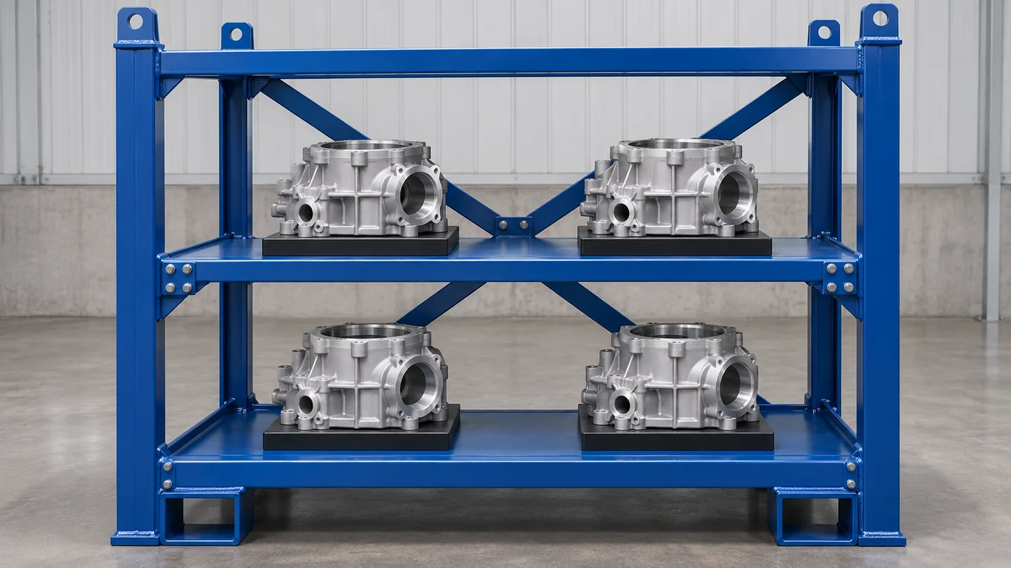
Choose a single-layer or multi-tier stillage from the positions that can actually be loaded and used, not the number of shelves on the sketch. Compare one layer when parts need a common top approach or a large handling-device envelope. Compare fixed internal tiers when every position remains accessible with the other levels occupied. An opening or removable level needs its own release, handling and stored position. In this guide, tiers are independent supports inside one frame, not separate complete stillages stacked above each other.
For packaging, production and purchasing teams specifying custom stillage racks, this decision defines how many supported part positions the quotation really provides. More drawn levels do not automatically mean more usable capacity.
Compare the same part set in both layouts
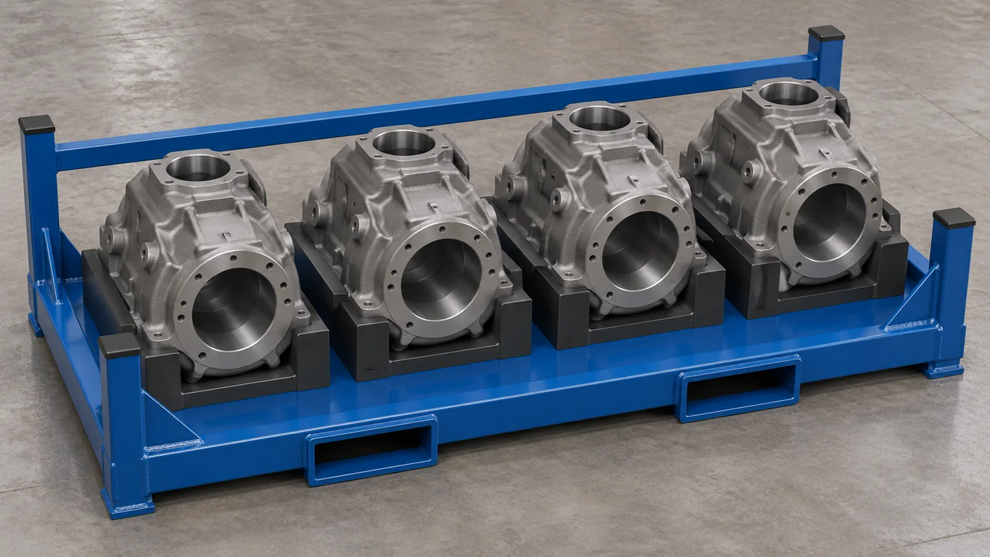
Consider several cast housings that must travel together. One arrangement places them side by side on a low base. Another places the same set on two internal levels. The low arrangement needs more floor area, while the layered arrangement introduces overhead structure and a different task at the lower level. Compare both with the same parts, contact restrictions and intended handling device.
Show the complete set and the actual removal order. If production can pick any housing next, each position needs the corresponding access. If the upper level must be emptied before the lower one can be used, state that sequence explicitly. Procurement can then compare the carrier with the real process instead of paying for positions the operation cannot reach.
| Arrangement | Starting condition | Main trade-off | Quotation input |
|---|---|---|---|
| Single layer | A common open approach to each part is needed | Larger occupied footprint for the same part set | Side-by-side contacts and complete load outline |
| Fixed independent tiers | All positions remain accessible within the available height | Upper supports reduce the free space around lower parts | Loaded section and first/last part paths |
| Opening or removable level | A defined sequence allows a level to move out of the way | Extra handling, release and retained/stored state | Moving level, device and storage position |
Common open approach. Send the supplier: Full horizontal layout.
Every level accessible. Send the supplier: Occupied section views.
Defined release sequence. Send the supplier: Handling and stored state.
Keep one layer when the approach needs open space
A single layer gives the designer an open area above the part supports. That can matter for a component that needs a large grip change, a broad lifting fixture or a particular rotation during seating. It can also make different positions visible from one working side. Draw the complete handling motion before deciding that the upper space is available for another tier.
The trade-off is the occupied footprint of the complete part set. Check that outline against the actual route and station. A low frame is not automatically easier to handle if its width blocks the required approach or the farthest part cannot be reached using the selected method.
Lowe's automotive stillage guidance starts with component geometry, presentation and handling. Use that part-first approach when comparing horizontal and layered layouts: the useful arrangement is the one that accommodates the job, rather than the one with the most attractive empty-frame photograph.
Count a tier only when its positions can be used
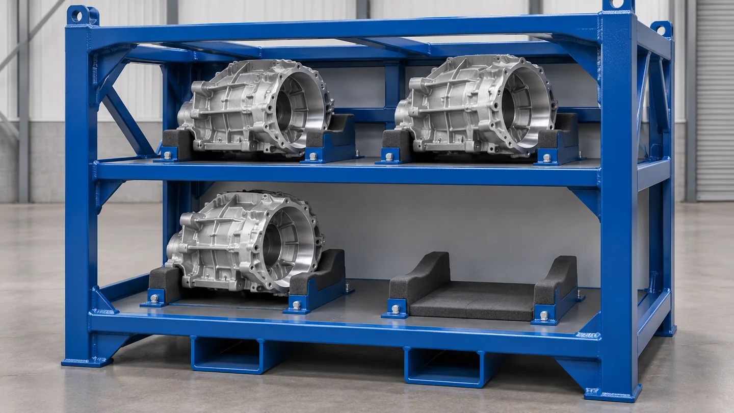
For fixed levels, dimension the free space from the part-support surface to the lowest member or loaded feature above it. Include protective materials and the highest part protrusion. A shelf-to-shelf distance on the frame drawing does not establish the working space around a seated component.
Then check the first and last position on each level. An empty front seat can make a demonstration look easy while the final rear part requires moving its neighbour. If removal order is fixed, draw that order. If it is flexible, test the positions that must work independently with adjacent parts still in place.
EasyLink's automotive rack comparison distinguishes usable internal space, packaging and loading clearance from the outside frame size. For internal tiers, extend that distinction to every occupied level rather than applying one overall internal height to the whole rack.
Give every level its own part supports
Independent internal tiers carry their parts on separate designed supports. They are not simply a way to pile components on one another. Mark the allowed contact areas for each level and show the part orientation, separation and restraints that belong to that position. If a component's cosmetic or thin surface must stay clear, keep that restriction on both proposed layouts.
Metkora's automotive transport-rack page discusses part-specific cradles and frame configurations. Its use of tier and stacking terminology also makes a useful purchasing distinction: ask whether a proposal adds internal part levels or describes stacking whole racks. Those are different drawings and different operating tasks.
The support-spacing guide addresses contact locations along a component. Use it after choosing the internal arrangement; it does not decide whether another shelf should sit above that component. Keep the layout choice and the detailed support design connected without treating them as the same question.
Include the task created by an opening level
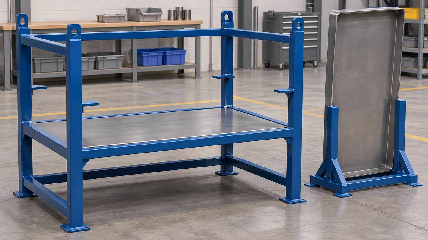
An upper tray that opens or is removed may create access to the lower parts. The proposal needs to show when that action occurs, what remains loaded, how the level is released and where it is held afterwards. A removable rectangle in a drawing is not a complete operating arrangement.
Show the intended handling method and the access needed to attach, release or grip the level. The plant should evaluate the actual task, including the empty tray where it is manually handled. HSE's manual-handling guidance identifies posture, distance, frequency, load and available equipment as relevant factors. Do not replace that task review with a generic reach or lifting number.
For a removed tray, include its stored position in the same area plan. For an opening level, show the retained-open envelope and the closure task before travel. Ask the quotation to identify the proposed support, release and retention arrangement; do not infer an assisted or powered mechanism from a concept picture.
Keep internal tiers separate from external stacking
Adding an internal level changes the load carried inside a single frame. Stacking complete stillages introduces interfaces and conditions between whole units. State both separately if the programme needs both, including the loaded and empty arrangements. A photograph of two shelves does not establish how many loaded frames can be stacked.
The stillage load and stacking guide explains the separate load questions. The loading-face guide helps choose the opening after the internal positions and removal order are understood. Neither a stacking feature nor an open side resolves an obstructed lower part by itself.
Five steps to a usable-position quotation
- Map the complete part set. Show each component, its allowed contacts and how many pieces must travel together.
- Draw the single-layer option. Place all supported parts side by side and include the actual occupied footprint and loading approach.
- Draw independent internal levels. Show the support surface, free height, obstruction and part path for every proposed layer inside one frame.
- Try the least accessible position. Check the last lower part with the upper level occupied, plus opening or removal and storage of any moving tray.
- Quote usable positions. Send the two layouts, handling sequence, loaded and return states, quantity and destination; compare the positions that can actually be loaded and used.
- Does the part need a common open top approach?Yes → Compare one layer.No → Can each fixed level be used?
- Can each fixed level be used?Yes → Compare fixed tiers.No → Define a moving-level task.
HAOFU develops stillage frames and contact arrangements from part and route inputs. Its covered multi-layer configuration provides an existing product reference for discussing separated levels, without setting the count or mechanism for your order. Begin with a part photo and a short quantity requirement, then add contacts, proposed positions, the least accessible handling task, return condition and destination for a developed quotation.
Send your part set and stillage layout requirement — the full engineering input list is optional for your first message.
Frequently Asked Questions
- Does multi-tier mean stacking complete stillages?
- Here it means separate supported levels inside one stillage frame. Stacking complete units is a different design condition with its own frame interfaces and load requirements.
- When is a single-layer stillage preferable?
- Compare one layer when components need a common top approach, a large lifting-device envelope or flexible access to each position. Include the resulting loaded footprint rather than assuming it fits the existing route.
- When do fixed internal shelves make sense?
- They are useful candidates when the repeated part arrangement fits the available height and every position can be loaded and removed with neighbouring levels occupied. Check the lowest and deepest positions before counting them as usable capacity.
- Can an upper tray be removed to reach the lower parts?
- It can be considered as a proposed configuration only with a defined empty or otherwise approved handling state, grip or device, release sequence and storage position. Include those actions and the tray in the quotation rather than assuming removal is effortless.
- Can parts rest directly on the components below them?
- That is a different load arrangement from independently supported tiers. If part-on-part contact is not permitted, show a separate designed support surface for each level and the required separation between components.
- What should I send for a layered stillage quote?
- Start with a part photo and intended quantity. Add the part drawing, permitted contacts, proposed positions per layer, loading sequence, handling device, loaded and return states, order quantity and destination as available.