How Much Top Clearance Does a Loaded Wire Mesh Container Need for Stacking?

Keep the entire top landing interface clear, not just the visible mesh opening. Establish a maximum loaded profile below the upper frame and corner landing zones; hold all parts, packaging, loose inserts, gate hardware, lids and restraints outside the upper container's approach and seating path. Derive the needed clearance from the actual top frame, stacking feet or cups, payload movement and intended loaded-stack condition. Send both containers' interface drawings and the worst loaded condition to the supplier before the frame and containment method are fixed.
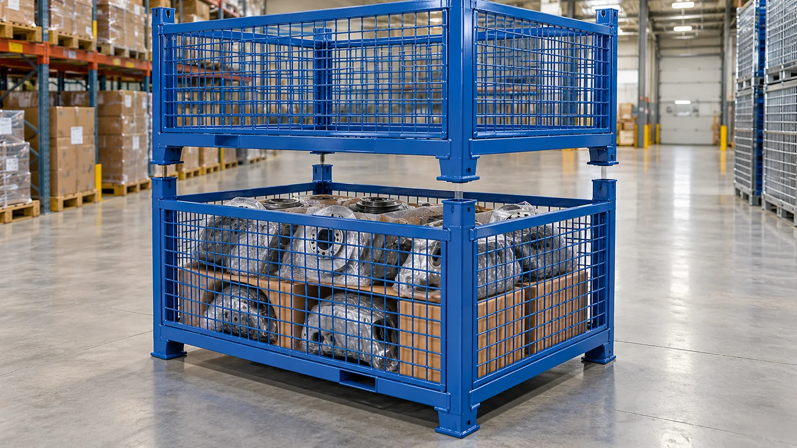
Keep the complete upper landing interface clear—not only the centre of the mesh opening. Define where the upper container's feet, corner guides or stacking cups travel as it approaches, seats and is removed. Set a maximum loaded profile below that envelope and include parts, packaging, loose inserts, the closed lid, gate hardware and any restraint. The required clearance is not a universal number: it comes from the actual two-container interface, credible load movement and the handling method. Send the supplier drawings of both units plus photographs or CAD of the worst loaded condition.
This is a loaded-stacking decision, not a generic warning against overfilling. The Rail Cargo Group EUR box-pallet specification issued in May 2025 shows an upper steel frame with positioning brackets and a defined loading-space marking. Morrison Industries describes stacking guides, lids and gates as configurable parts of a wire-mesh-container design, while Nashville Wire shows how stacking feet, access gates and security lids coexist on commercial container families. Their dimensions and ratings are not HAOFU specifications; the useful lesson is to design load control and the stacking interface together.
Define the landing envelope before the fill line
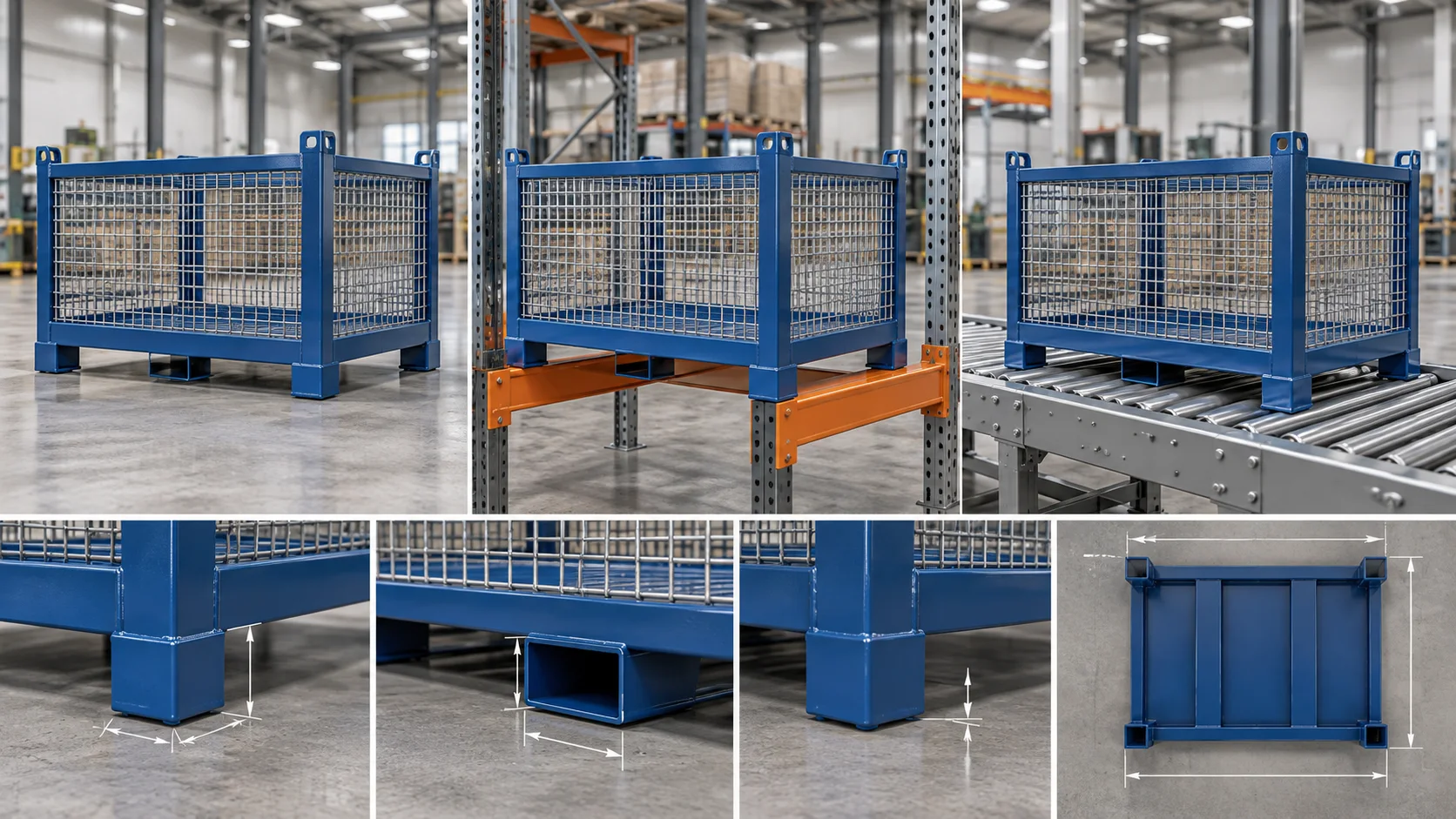
Start with an overlay of the lower container's top frame and the upper container's underside. Mark the four corner landing features, any intermediate guides and the path used while the upper unit descends. A foot or cup may move inward or outward before it reaches its final seat, so the protected zone can be wider than the final contact patch. Repeat the review for removal, including the small lateral movement created by normal forklift placement.
Now draw a horizontal fill datum for the contents. The datum must sit below the lowest relevant part of the landing envelope with enough room for the actual payload and packaging behaviour. A rigid tray may remain stable; loose bags, tall components or flexible separators can rebound, lean or migrate. Use the worst representative condition instead of the neatest packed photograph.
| Input | What to measure or show | Design response | RFQ evidence |
|---|---|---|---|
| Upper unit interface | Feet, corner cups, guides, frame rails and their approach path. | Reserve a keep-clear landing zone around every feature. | Underside drawing and stacked section view. |
| Payload and packaging | Tallest part, dunnage, bags, trays, loose inserts and likely movement. | Set a maximum loaded profile that remains below the interface. | Loaded photographs, part CAD and worst-case pack list. |
| Lid or cover | Closed height, hinge sweep, latch position and stacking-feature openings. | Keep the complete closed assembly out of landing paths. | Open and closed lid sections. |
| Gate and restraint | Gate closure, strap, bar, tray or retainer in its transport state. | Control tall contents without obstructing stacking or release access. | Transport-state drawing and operator sequence. |
| Handling variation | Fork entry, approach direction, placement tolerance and removal path. | Give guides enough entry room while protecting the payload. | Route, truck/fork details and trial condition. |
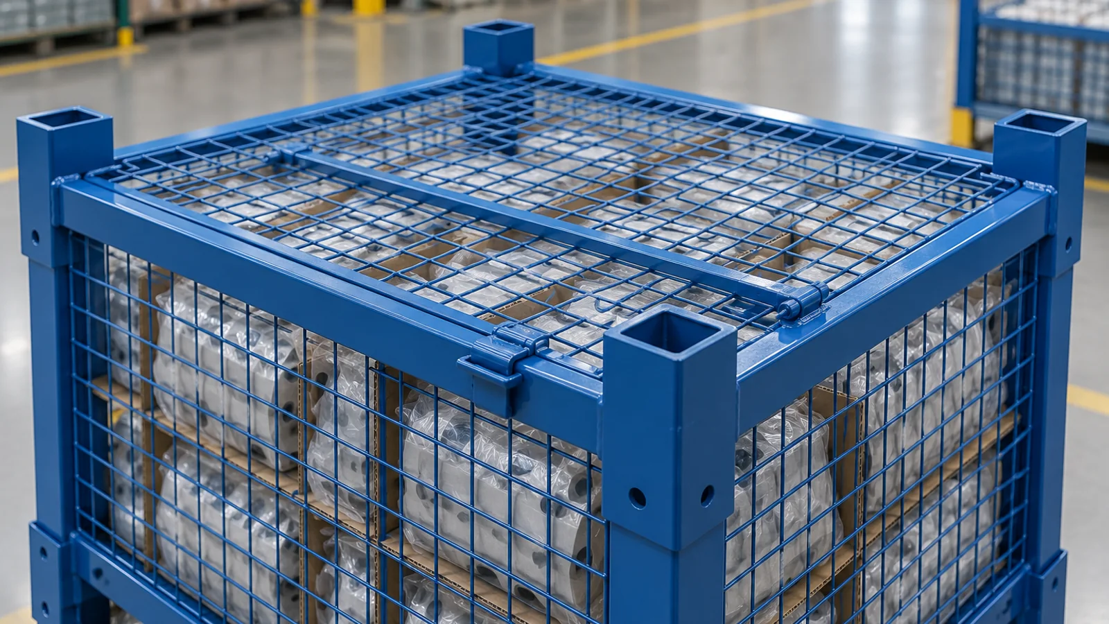
Set a visible fill datum below the upper frame and allow for packaging rebound or part movement during the route.
Check the complete closed profile, hinges and latches while keeping all stacking feet or corner landing zones exposed.
Use trays, straps or retainers to control tall contents without placing hardware in the upper unit's landing path.
Choose containment from the way the load can move
An open-top container can work when the parts and packaging stay below the fill datum throughout the route. Tall or springy contents may need an internal tray, strap, retaining bar or lid. Choose the device by the motion it must control, then check its own transport position. A restraint that rises above the top frame, a loose strap end or a latch sitting in a corner cup can defeat the intended clearance even when the parts themselves are low enough.
A lid can provide useful containment, but it does not automatically make the container stackable. Show its closed section, hinge knuckles, handles and latch hardware in the same interface overlay. If the lid is removable, define where it is stored during loading and how the operator confirms it is fully seated before stacking. The Zamko mesh-cage overview notes that actual stacking decisions depend on the load, product height and site rules, and it presents hinged lids as a containment option. That is a sound prompt for project inputs, not a transferable stack rating.
Coordinate access gates with the transport state
A drop gate or hinged side panel may be used during picking, but its closed position belongs in the stacking review. Confirm that the gate is positively seated, its handles remain inside the permitted envelope and no loose component can enter a corner landing zone. If replenishment happens while the containers remain stacked, use the separate access-gate replenishment guide; the question here is whether the closed, loaded container presents a clear and repeatable top interface.
Use trays or dunnage to create a stable loaded profile
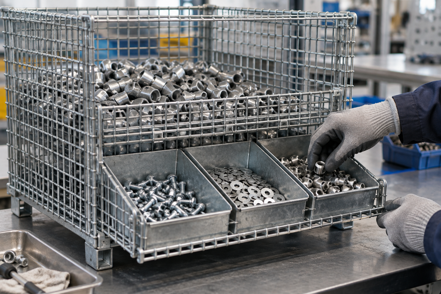
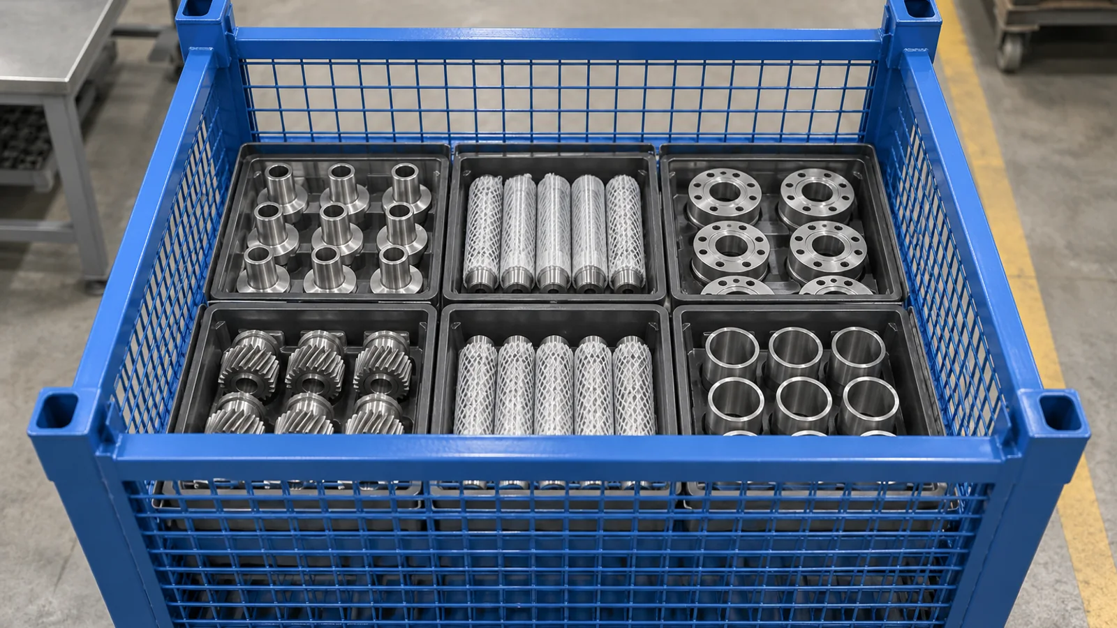
When components vary in height, a fixed fill line on the mesh alone may be hard to control. A top tray, pocket array or shaped dunnage can define where the tallest feature sits and prevent parts from leaning into the landing zone. Its attachment must remain accessible and outside the upper unit's path. For small parts in a deep container, first solve the operator's reach and extraction task with the deep-container picking guide; do not raise the load simply to improve access without rechecking stacking.
Check the complete placement and removal cycle
A section drawing proves only one instant. Review the upper container approaching from the actual fork direction, entering the guides, seating on all intended contacts and lifting away again. Include a credible placement offset rather than assuming perfect alignment. Look for tall contents touching the upper base, packaging entering a cup, a lid handle catching a foot or a gate latch blocking a guide.
- Overlay the upper and lower containersUse actual top-frame, foot, cup, guide and corner geometry.
- Trace the complete landing pathCheck approach, location, seating and removal—not only the final stacked position.
- Set a maximum loaded profileInclude parts, packaging, loose inserts and credible movement during handling.
- Choose containment that preserves the interfaceCoordinate the lid, gate, tray, strap or retainer with the protected upper zone.
- Trial the worst loaded conditionLoad, stack, unstack and inspect with representative contents and intended handling equipment.
Five steps to prepare the loaded-stacking input
- Overlay the two container interfaces. Provide the lower top frame and upper underside, including feet, cups, guides and corner details.
- Trace approach, seating and removal. Reserve the complete landing path, not only the final contact areas.
- Set the maximum loaded profile. Include the tallest part, all packaging and credible movement on the real route.
- Choose the containment state. Show lids, gates, trays, bars, straps and latches exactly as they travel and stack.
- Trial the worst loaded condition. Place, stack and remove representative units with the intended handling equipment, then inspect the interfaces.
What to send for a custom wire mesh container quotation
Send the payload list, part CAD or loaded photographs, maximum fill profile, packaging and loose-insert details, top-frame and stacking-interface drawings, lid/gate/restraint transport states, loaded stack quantity, forklift approach, floor and route conditions, quantity, destination and the proposed acceptance trial. Review custom wire mesh containers, then send the loaded condition and interface drawings for a quotation.
Frequently Asked Questions
- How much top clearance does a loaded wire mesh container need?
- There is no universal clearance. Derive it from the upper container's feet, cups or guides, their approach path, the lower top frame, payload movement and the intended loaded-stack condition.
- Which area must stay clear when mesh containers are stacked?
- Keep every landing and guide path clear, including the four corners, intermediate contacts and the space used as the upper unit approaches, seats and lifts away.
- Can the load rise above the top frame if the stacking corners are clear?
- Only if the complete upper container and handling path have been reviewed and remain clear. A part or package in the centre can still contact the upper base, so use a defined maximum loaded profile.
- Does a lid automatically control loaded stacking clearance?
- No. Review the closed lid height, hinges, handles and latches against the upper landing interface. The lid must contain the load without obstructing stacking features.
- How can tall parts be kept below the stacking interface?
- A shaped tray, pocket array, strap, bar or lid can control the loaded profile. Select the device from the actual part motion and keep its attachments and release hardware outside the landing path.
- What should I send for a stackable wire mesh container quote?
- Send payload and packaging details, loaded photographs or CAD, maximum fill profile, both stacking-interface drawings, lid/gate/restraint states, handling route, quantity, destination and a proposed stacking trial.