Wire Mesh Container Bases for Floors, Rack Beams and Roller Conveyors

Start a wire mesh container base design with every surface the unit will touch. Corner feet can establish a stable floor or stack seat, but rack storage needs the feet or lower frame to land on the actual beam profiles without unintended overhang. A roller conveyor normally needs continuous support lines aligned with the conveying direction and long enough to bridge the roller pitch and transfer gaps. Put floor joints, rack beams, roller spacing, fork entry, stacking features and loaded and empty states on one interface drawing before choosing the base layout.
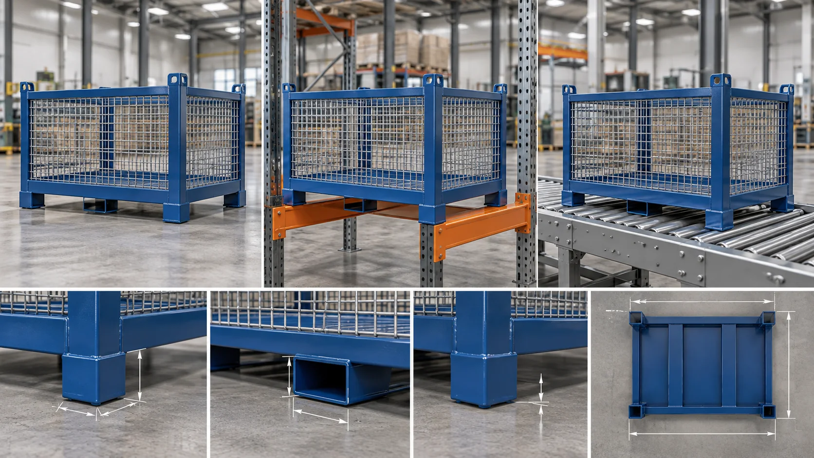
Design the bottom of a wire mesh container from every surface it must cross and land on. Corner feet can work on a flat floor or matching stack seat, but rack beams need the feet or lower frame to land fully on known beam profiles. Roller conveyors usually need continuous support lines that run in the conveying direction and remain supported across the roller pitch and transfer gaps. Show floor joints, rack beams, roller axes, fork entry, stack interfaces and loaded and empty states on one drawing before a supplier chooses feet, skids or a combined lower frame.
Industry pages confirm that these are different interfaces. Schaefer Behältertechnik distinguishes mesh boxes from steel pallets specifically offered with runners for roller conveyors. GURA Intralogistik explains why steel runners, roller pitch and infeed forces must be considered together for wire mesh boxes. GEBHARDT lists full and empty wire mesh pallets among the units its conveyor handles and shows that guides, stops and transfer details belong to the conveyor system. The buyer's missing step is a single support map that both the container and equipment suppliers can review.
Compare the surfaces before drawing the base
| Landing or transfer | Base condition to define | Information to send |
|---|---|---|
| Flat factory floor | Stable contact plane, underclearance and ability to cross expected joints or small debris. | Floor condition, joint profile, approach, set-down direction and handling equipment. |
| Another container | Feet and stacking seats meet without wall, gate or accessory interference. | Loaded and empty stack views, orientation, loose components and intended stack arrangement. |
| Pallet-rack beams | Support points or lines sit fully on the two beam profiles through the allowed placement tolerance. | Beam section, front-to-back spacing, clear span, support direction, guides and stop details. |
| Roller conveyor | Continuous skids bridge successive rollers and transfer gaps in the travel direction. | Roller diameter, pitch, axes, driven zones, transfer detail, guides, stops and infeed method. |
| Chain or mixed transfer | Contact lines match the chain tracks and clear any lift or cross-transfer mechanism. | Equipment layout and elevation drawing from the conveyor integrator. |
Define the feet, support plane, underclearance and the floor joints or debris they must cross.
Put the actual beam profile, clear span and support direction on the container drawing.
Use continuous contact lines in the conveying direction and check each transfer gap.
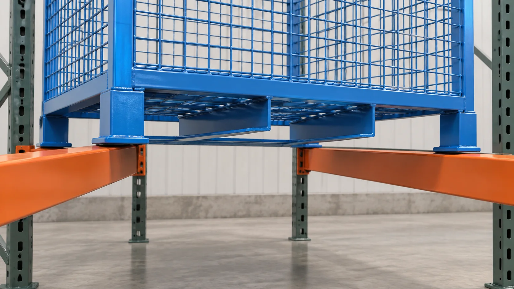
For rack beams, map the two support lines
Do not send only the rack bay width. Show the front and rear beam cross-sections, the clear distance between them, the usable top surface, any step or lip, and the container orientation. Then mark the two areas of the container base that are allowed to carry load. If corner feet are intended to land on the beams, their complete contact area should remain on the support surface through the agreed placement variation. If the lower perimeter frame or runners carry the unit instead, show which members cross each beam.
Also draw the pickup and deposit action. Fork pockets, lower guides, stacking feet and the rack beam can compete for the same space. A guide that helps the operator centre the unit must not become an unreviewed load point. The relevant question for the supplier is: after the forks withdraw, which exact steel surfaces carry the complete container?
For rollers, direction and continuity decide the skid layout
A roller conveyor supports a series of narrow contact lines. The container needs lower members that remain supported as the rollers turn and as the unit crosses between conveyor sections. Ask the conveyor integrator for roller diameter, pitch, axes, travel direction, guide clearance, stop position and every transfer gap. Then orient continuous skids so that several rollers can support the unit at each stage of travel. GURA's guidance uses three supporting rollers as a conveyor-design reference; use the integrator's actual calculation and equipment data for the project rather than treating any web example as a HAOFU rating.
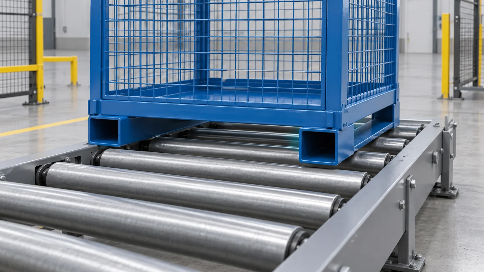
Pay special attention to entry from a forklift, lift table or turntable. A base that travels well on straight rollers can still catch at a gap, collide with a side guide or lose support during a 90-degree transfer. Check the empty container too: a folding wall, loose divider or gate must not drop into the base path or block the equipment sensor.
Keep support, fork access and stacking on separate drawing views
The bottom plan should identify the load-carrying feet or skids. A second view should show fork or pallet-truck entry and underclearance. A third should show how one container sits on another. Review the views together, but do not let an open fork pocket stand in for a support surface or assume that a stacking foot automatically fits a rack beam. The empty-return guide covers folding and loose components; the access-gate guide covers replenishment; and the deep-container guide covers last-piece retrieval.
UIC 435-3 is a first-party quality standard for one defined reusable steel EUR box-pallet format. Its scope includes manufacture, testing and marking of that specific 800 × 1200 mm carrier. Use it when that exchange format is actually required; do not apply its geometry to a custom container simply because both products use wire mesh.
- List every landingInclude floor, stack seat, rack beams, rollers and the transfers between them.
- Map the support linesRecord surface width, clear span, direction, height and interruptions.
- Draw the complete baseCoordinate feet, skids, underclearance, fork entry and stacking features.
- Trial every handoffUse the intended equipment, representative load and loaded and empty states.
Five steps to specify the bottom interface
- List every landing and transfer. Include floor, stack, rack, rollers, chains, lift tables and the handoffs between them.
- Collect the receiving geometry. Obtain beam profiles, support spans, roller pitch and axes, transfer gaps, guides and stops from the equipment owner.
- Map the contact and clearance. Separate carrying surfaces from fork entry, stacking locators, moving panels and sensor or guide clearances.
- Choose feet, skids or a combined frame. Compare each candidate against every loaded and empty state rather than optimising one station.
- Trial the complete route. Use the intended handling equipment, representative load and worst transfer before production release.
What to send for a custom wire mesh container quotation
Send the part or package drawing, total loaded mass and centre-of-gravity information; internal quantity and orientation; container outside and inside envelope; floor and joint condition; stacking arrangement; rack-beam profile and spacing; roller or chain conveyor layout, direction and transfer gaps; fork or pallet-truck data; guides, stops and sensors; loaded and empty states; quantity; and the sample route-trial task.
Need a container base that fits more than one handoff? Review custom wire mesh containers, then send the support map, container contents and equipment drawings for an engineering quotation.
Frequently Asked Questions
- Can a wire mesh container sit directly on pallet rack beams?
- It can when the container support points or lower frame land fully on the actual beam profiles and the complete container is approved for that use. Send beam sections, spacing, orientation and placement tolerance with the RFQ.
- What base is needed for a mesh box on a roller conveyor?
- A roller conveyor commonly needs continuous lower skids aligned with the conveying direction. Their length and spacing must suit the real roller pitch, transfer gaps, guides and stops.
- Are corner feet enough for every support surface?
- No. Feet can establish a floor or stacking seat, but they may not bridge rack beams or roller gaps. Map every receiving surface before choosing feet, runners or a combined frame.
- Which conveyor details should I send to the container supplier?
- Send roller or chain layout, travel direction, pitch, support width, elevations, transfer gaps, guides, stops, sensors and the forklift or lift-table infeed method.
- How should a custom wire mesh container base be tested?
- Trial a production-intent sample through every loaded and empty handoff using the intended handling and storage equipment, including the most difficult rack placement and conveyor transfer.
- What is needed for a wire mesh container quotation?
- Send the contents, loaded mass and centre of gravity, container envelope, floor and stack conditions, rack-beam and conveyor drawings, fork or pallet-truck data, route, quantity and trial requirements.