Automotive Rack Loading Access: Define the Hand, Tool and Lift-Assist Envelope

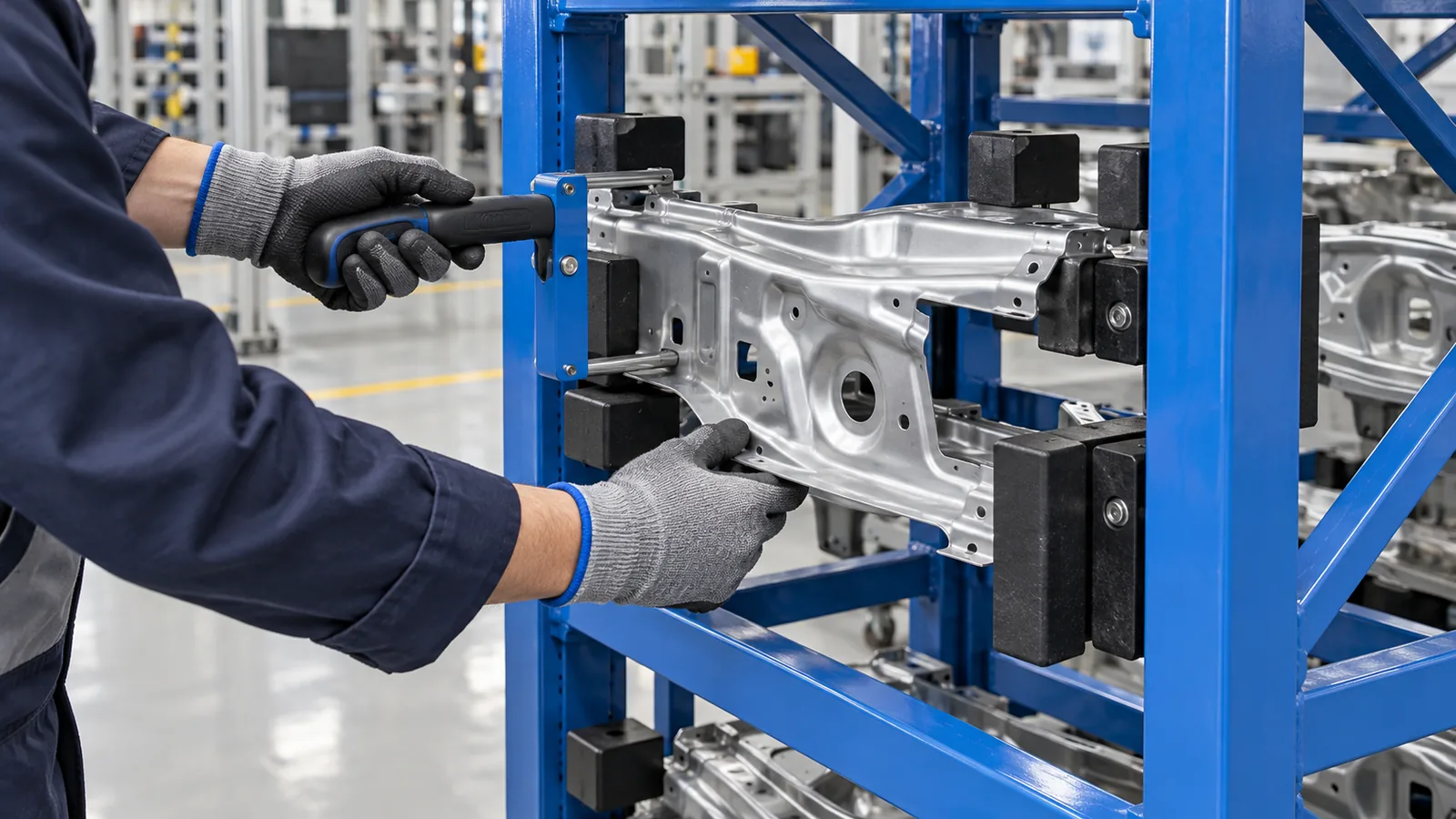
Define an automotive rack loading-access envelope by combining the part's swept path with the space used by hands, grips, lift-assist tooling or an end effector. Include approach, seating, release, empty-tool withdrawal and recovery at the most constrained rack position. Then place posts, braces, stops and moving bars outside that envelope. Send the supplier current part CAD, grip points, loading-device geometry, station layout and a motion study so the opening can be reviewed before the rack frame is fixed.
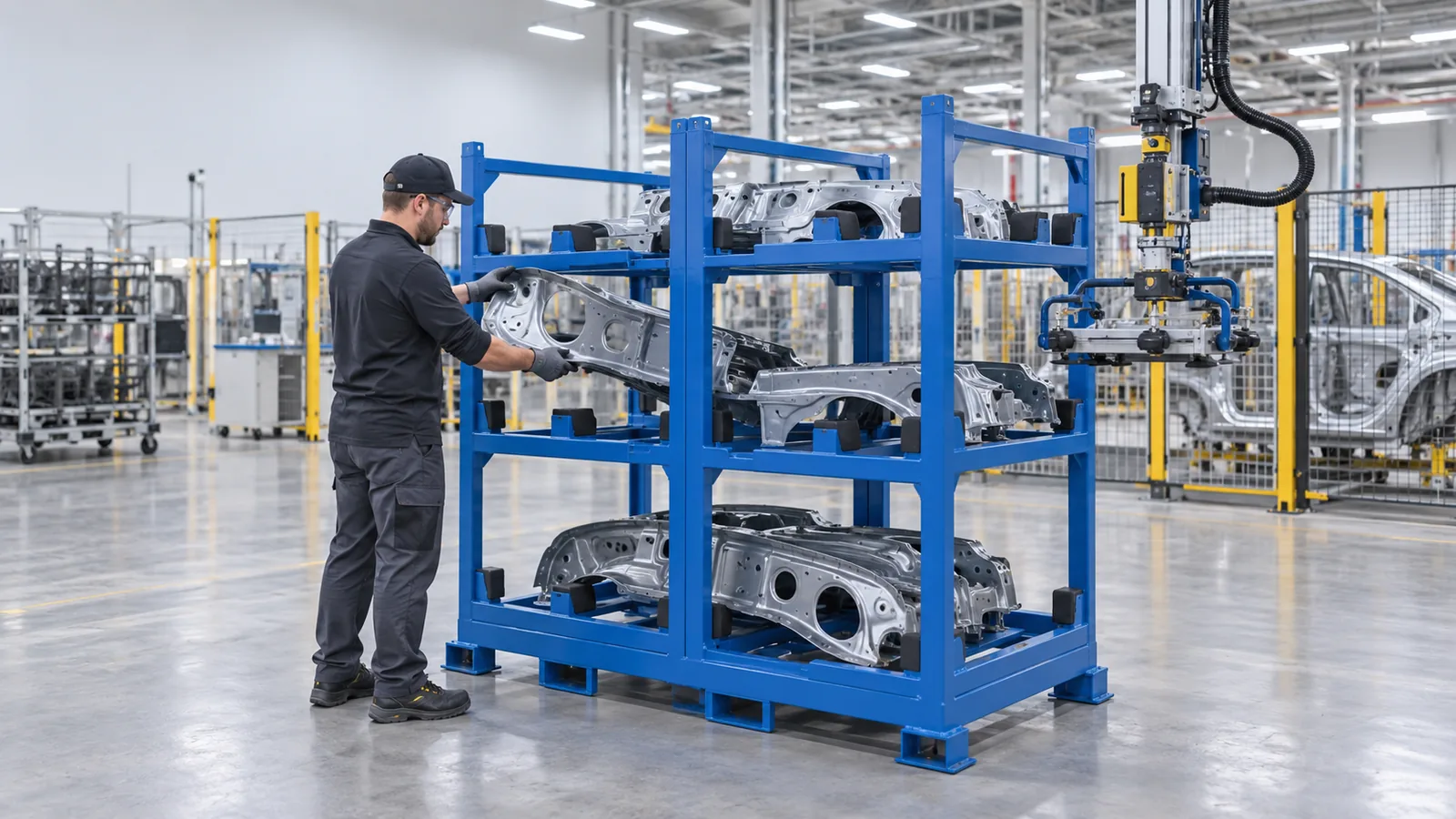
Design the rack opening around the complete loading motion, not only the static outline of the part. A usable access envelope includes the component, both hands or the full lift-assist tool, grip changes, approach angle, seating movement, release action and empty-device withdrawal. It also includes the least accessible position in the rack—not just the easiest front bay. Put that swept volume into the rack layout before fixing posts, diagonal braces, retaining bars or locators. For a quotation, send current part CAD, approved grip and contact zones, the loading-device model, workstation constraints and a short motion sequence.
This question is narrower than a general rack RFQ. PSS Rack describes concept work around loading configuration, contact locations and clearances, while Morrison Industries frames automotive racks around part orientation, access and the handling path. SailRail's walk-in cart example shows how an opening can be deliberately shaped around operator access. The buyer's practical decision is which moving envelope the rack must preserve for the actual station and device.
Start with a swept volume, not a front-view gap
A front elevation can show that a part fits between two posts, but it cannot show whether fingers become trapped behind the part, whether a vacuum head clears the upper cross-member or whether the empty lift-assist tool can leave after the part is seated. Build the envelope from successive positions: pickup pose, approach, any rotation, first locator contact, final seat, grip release and withdrawal. Add the tolerance or compliance used by the loading device, then inspect the path against every rack member.
For manual tasks, record where each hand starts, where the grip changes and where the hands exit. The NIOSH Revised Lifting Equation guidance identifies horizontal and vertical hand location, travel distance, asymmetry, frequency, duration and coupling as relevant lifting inputs. That resource does not approve a rack design, but it explains why “loaded by hand” is too vague for an engineering brief. The plant's ergonomics and safety team should review the real task.
| Loading method | Envelope to model | Buyer input for the RFQ | Typical rack-layout question |
|---|---|---|---|
| Two-hand manual load | Part, both hands, grip changes, wrist/forearm clearance and hand withdrawal. | Part mass, pickup height, grip points, station height and intended sequence. | Can the operator seat and release the part without reaching around a post or sharp frame edge? |
| Manual tool or gauge | Tool body, handle, fastener or gauge direction and the tool-removal path. | Tool dimensions, operating angle, access side and task performed in the rack. | Does a brace block the tool before the part reaches its controlled position? |
| Lift-assist manipulator | Part, gripper, wrist, controls, hose/cable bend, compliance and unloaded withdrawal. | Tool CAD, suspension point, working radius, motion study and release sequence. | Can the gripper release and leave without lifting the part off its locators? |
| Robot/end effector | Part and tool swept volume, cable dress, approach tolerance and recovery access. | Integrator CAD, datum scheme, robot path, sensor needs and fault-recovery task. | Are the rack datums accessible without creating a collision during normal variation? |
Map both hands, grip changes and the hand-withdrawal path—not only the component outline.
Include the tool body, wrist, controls, hose or cable and the empty-tool withdrawal motion.
Use the integrator's swept volume, datum and tolerance model, while preserving recovery and maintenance access.
Separate part clearance from device clearance
Part clearance protects the component as it enters and leaves. Device clearance protects the method used to move it. They overlap but are not identical. A narrow opening may pass the component while blocking an operator's knuckles, a clamp handle or a gripper wrist. Conversely, making the whole front face open may weaken the intended brace layout or allow uncontrolled movement. The useful drawing shows the required envelope first, then asks the rack engineer to place the structure around it.
Mark three zones in the CAD review: the part swept volume, the hand/tool swept volume and the rack's permitted structure zone. A fourth zone can reserve sightlines to labels, locators or confirmation sensors. Keep these distinct from approved support and restraint contacts. For advice on preventing reversed loading, use the separate rack orientation error-proofing guide; for contact material and attachment, see replaceable contact pads.
Check the first, last and most constrained positions
Multi-position racks rarely provide equal access to every bay. Corner posts restrict the end positions; upper frames reduce headroom; already loaded parts can block the next path; a retaining bar can create a second motion that competes with the loading tool. Identify the position with the smallest usable approach cone and review it first. Then check the loading order, because a path that works into an empty rack may disappear after adjacent positions are filled.

Allow for release, withdrawal and recovery
The device does not vanish when the part reaches its locator. A vacuum cup may need room to vent and lift away; a clamp must open; a mechanical hook needs an escape direction; an operator must remove both hands. Model the unloaded device after release and show how it exits without dragging the part across a protected surface. For automated or assisted tasks, also show a safe recovery path for a stopped cycle. Recovery and guarding remain the responsibility of the plant and equipment integrator, but the rack must not consume the agreed space.
Coordinate access with the rack structure
Once the envelope is visible, compare structural options. A higher cross-member may preserve the tool path but change frame behaviour. A removable bar may open the face but adds an operating step and a retained open position. An offset brace may protect the opening while consuming side clearance. These are project engineering decisions; the quotation should identify the selected concept and the evidence expected before production.
- Freeze the part and poseUse current CAD, orientation, approved contacts and actual grip points.
- Capture the complete deviceModel hands, lift-assist tooling or the robot end effector with hoses, cables and controls.
- Trace approach, seating and exitUse a swept volume through every motion, including release and empty-tool withdrawal.
- Place rack members around the motionResolve posts, braces, bars and locators without consuming the access envelope.
- Trial the worst positionLoad, release, withdraw and recover at the most constrained rack position.
Five steps to prepare a loading-access brief
- Freeze the part and pose. Provide current CAD, revision, loaded orientation, permitted contacts and the grip points actually used.
- Capture the complete loading device. Include hands, gloves, tools, gripper, controls, hoses, cables and compliance—not a simple centreline.
- Trace approach, seating and exit. Record successive poses through pickup, insertion, location, release and empty-device withdrawal.
- Place rack members around the envelope. Review posts, braces, locators, retainers and neighboring parts against the same swept-volume model.
- Trial the worst position. Use representative parts and the intended device to load, release, withdraw and recover at the most constrained bay.
What to send for a custom automotive parts rack quotation
Send the part CAD and revision, part mass and centre-of-gravity information, loaded orientation, approved support and no-contact zones, manual grip points or loading-device CAD, approach and withdrawal motion, station and floor constraints, rack position count, loading order, handling route, quantity, destination and the sample access task. Review custom automotive parts racks, then send the part and loading-device files for an engineering quotation.
Frequently Asked Questions
- What is a rack loading access envelope?
- It is the three-dimensional space used by the part, hands or loading device during approach, seating, release and withdrawal. Rack posts, braces, stops and neighboring parts should be reviewed against that complete swept volume.
- Is part clearance enough for a manually loaded automotive rack?
- No. The opening also needs space for both hands, grip changes, gloves, wrist and forearm movement, and hand withdrawal after the part is seated.
- What lift-assist information should the rack supplier receive?
- Send the tool or gripper CAD, suspension point, wrist and controls, hoses or cables, working radius, approach poses, release action, empty-tool withdrawal and the station layout.
- Which rack position should be checked first?
- Start with the position that has the smallest approach cone or the most interference from posts, upper levels, adjacent loaded parts or retaining bars. Then check the full loading order.
- Does this guide replace an ergonomics or machine-safety review?
- No. It helps define geometry for a rack quotation. The buyer's ergonomics, safety and equipment teams must assess the actual task, guarding, forces and operating procedure.
- What should I send for an automotive rack loading-access quote?
- Send current part CAD, revision, mass and centre of gravity, approved contacts, grip points, manual or device loading model, approach and withdrawal motion, station constraints, rack positions, route, quantity and trial task.