Automotive Rack Error Proofing: Design the Load Direction Into the Locator

A rack prevents loading-orientation mistakes most effectively when its physical locator distinguishes the intended pose from the plausible wrong ones. Start with the approved part datum and permitted support zones, then draw the operator or fixture entry motion. If a left/right, front/back or rotated part could still sit in symmetric supports, add an offset key, stop or entry constraint that meets a non-sensitive feature first. Keep visual marks as a supporting cue, not the only defence. Send the current CAD, part revision, restricted surfaces, orientation views and loading path so the supplier can design and trial the locating interface.
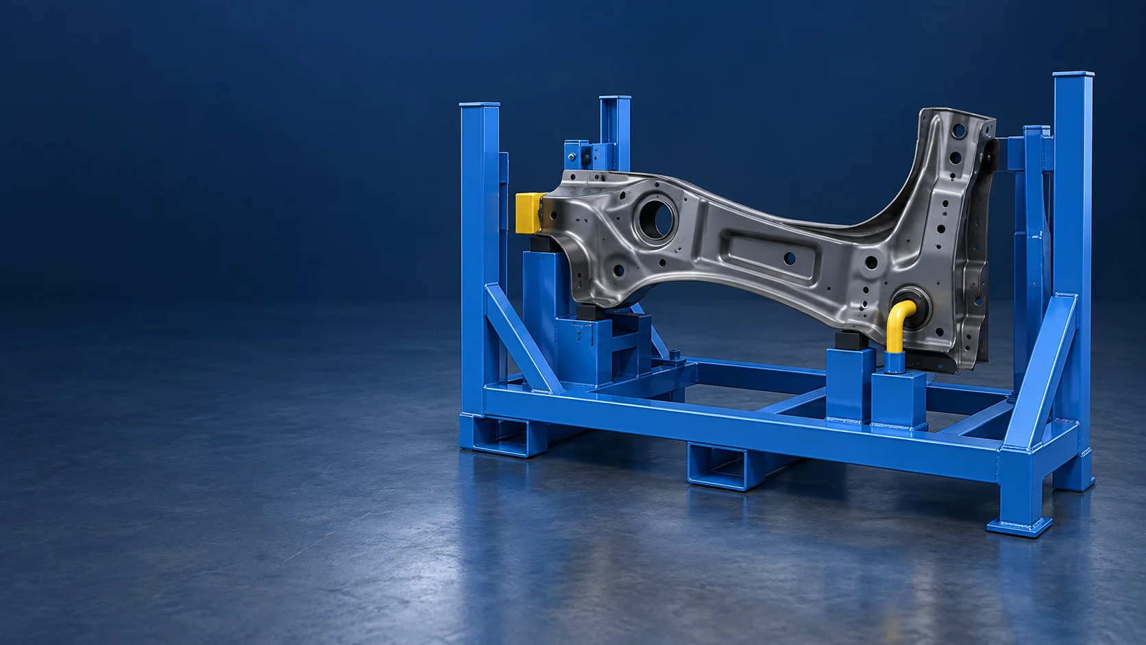
Use a physical locator to distinguish the correct part pose from the wrong one before the part reaches its intended supports. Begin with the approved datum, permitted contact zones and the real loading motion. If a mirrored, reversed or rotated component can sit in symmetric supports, add an offset key, stop or guided entry feature that the wrong pose meets first on a non-sensitive area. A colour mark can help an operator, but it is not the same as a locating interface. Give the supplier the current CAD, left/right or revision status, restricted faces and the complete hand or fixture path so the rack can be designed around the actual loading task.
Useful industry examples start with part geometry and orientation. Nefab’s rack-dunnage overview shows why a carrier is engineered around the part and its protection interfaces. PackIQ’s steel-rack guidance includes part orientation and handling in the design brief. PSS Rack similarly places CAD, loading configuration and dunnage in the project conversation. The next decision is more specific: which physical feature rejects a plausible wrong orientation without adding a new contact risk or blocking the correct loading motion?
When does an automotive rack need error-proof loading orientation?
Review the locating layout when the component has a handed version, an asymmetric face, an orientation-sensitive surface, a feature that must stay accessible, or a load path that changes when the part is turned. Start by placing the intended pose and the likely wrong poses in the same 3D space: mirrored left/right, 180-degree rotation, front-to-back reversal and any tilted entry an operator or fixture could make. If a wrong pose cannot reach the first support because the geometry already rejects it, an added key may not be necessary. If it can reach the pads or nest, the rack drawing needs a deliberate response.
| Condition to review | Practical starting strategy | What must be checked |
|---|---|---|
| Correct and reversed parts both rest on the same pads | Use a datum seat plus an offset key or stop. | The wrong pose meets the key before restricted surfaces touch. |
| Part is loaded along a narrow hand or fixture path | Use guide geometry that favours the correct entry path. | Grip, tool, fixture and exit clearance remain workable. |
| Left and right parts look similar at the station | Use a physical asymmetry and a visible part/position cue. | The key does not become a duplicate mixed-variant layout decision. |
| Part has delicate or functional faces | Place the rejection feature at an agreed robust zone. | Support, restraint and key contact are each shown separately. |
| One part revision changes a locating feature | Recheck the full datum/key model before reuse. | Current CAD, revision status and sample-trial scope are aligned. |
A colour, arrow or part ID can guide loading, but it does not stop a mirrored or rotated part from entering a symmetric seat.
Known supports can carry the part while still allowing a reverse orientation. Compare each wrong pose before release.
Let the intended datum seat first, then use an offset feature so an incorrect pose meets a stop before restricted contact occurs.
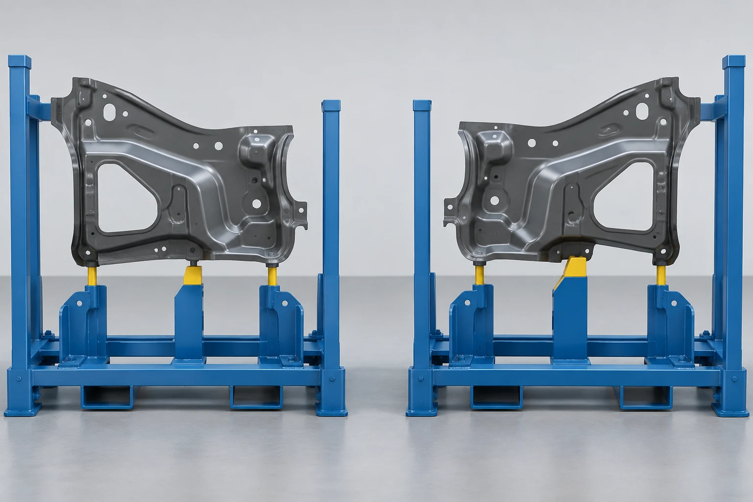
Build from the datum, not from a label
A useful locating scheme gives the part a repeatable starting reference. Mark the intended datum surfaces, the permitted bearing zones and the faces that cannot take a locating or rejection contact. Then show the direction in which the part moves into the rack. The datum may be a robust casting feature, mounting face or other buyer-approved reference; the choice belongs on the project drawing, not in a generic rule.
Next, look for the first point where a wrong orientation can be stopped without forcing an operator to twist, drag or force the part into place. An offset block, keyed opening or guide can work when its relationship to the part is intentional. The aim is not to add more metal around the part. It is to make the correct pose the natural route and make a wrong pose visibly stop early.
Separate support, restraint and error-proofing functions
One locator can sometimes do more than one job, but the drawing should still name the function of every contact. A support carries the part in its stored position. A restraint limits movement in the route. An error-proof feature distinguishes an incorrect orientation. Combining these roles without showing the contact purpose makes review harder, especially where a sensitive coating, seal face or cosmetic region is involved.
This guide does not replace the material/contact approval process. For attachment and changeout of a protective pad, see replaceable automotive rack contact pads. For bearing versus lateral restraint on a machined component, see the machined-casting support guide. For a controlled family of variants, see shared, divided and dedicated rack positions.
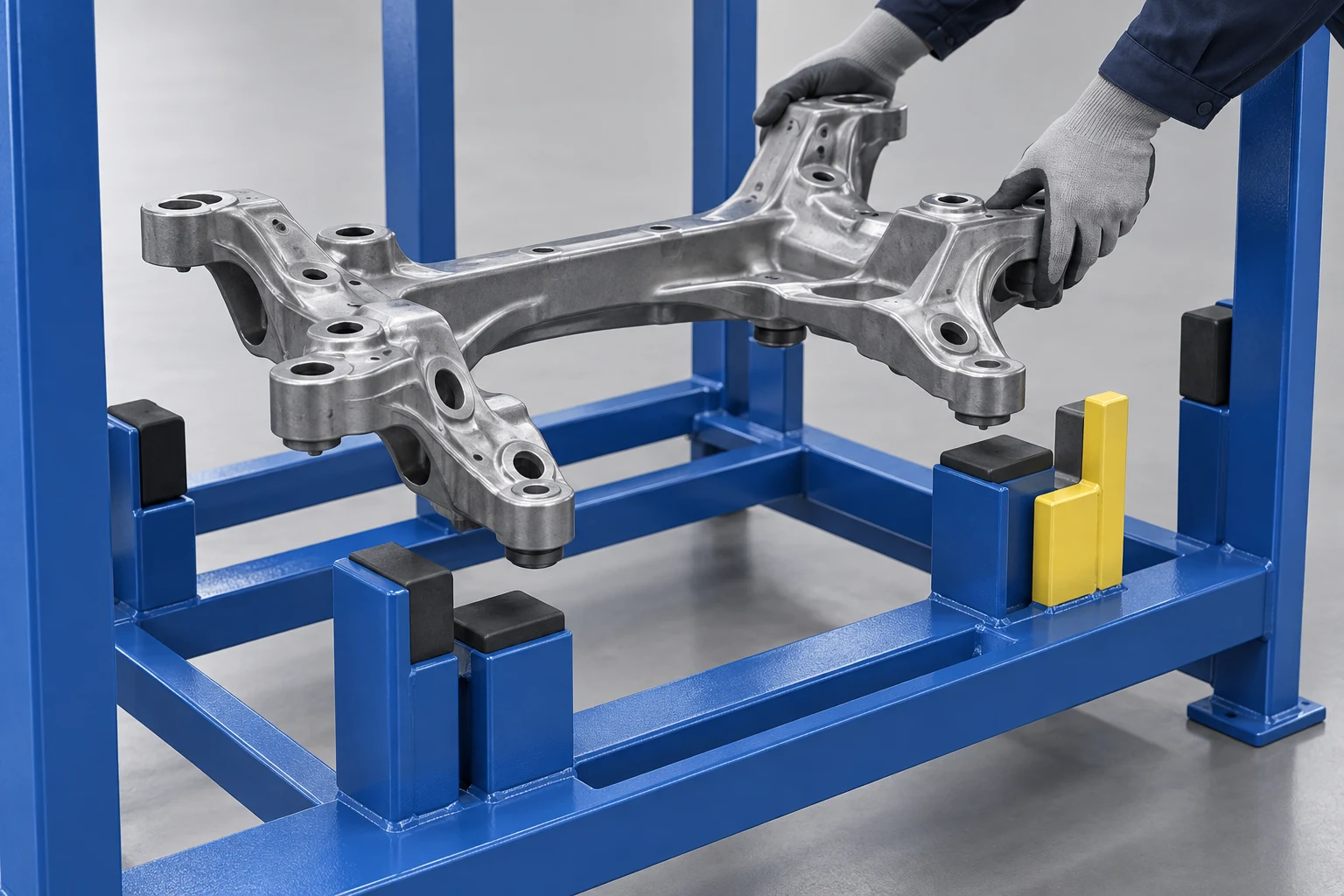
Trial the wrong pose as deliberately as the correct pose
A CAD review can reveal obvious clashes, but representative loading is where the part, grip, visibility and locator sequence meet. Try the intended pose first, then the credible wrong orientations identified in the review. Watch where the part first contacts, whether the operator can see the rejection point, and whether a wrong pose could bypass the key through a tilted or alternate entry. Record any drawing change before the layout is released.
A September 2026 update reported that Suppliers Partnership for the Environment had published circular automotive-packaging guidance addressing the whole packaging life cycle, including repair and return considerations. That is useful context for designing serviceable, reviewable carrier interfaces; it is not a HAOFU specification or approval. The part drawing and the buyer’s route remain the source of truth for a project.
- Freeze the part poseUse the current CAD or agreed sample and identify left/right, revision and intended loaded orientation.
- Map datum and no-contact zonesSeparate the permitted support datum from sensitive, functional or clearance-critical faces.
- Draw the entry motionInclude operator hands, grippers, fixtures, approach direction and clearance around the part.
- Add an offset key or stopMake a wrong pose meet a non-sensitive obstruction before it reaches the intended supports.
- Trial correct and wrong posesCheck loading, removal, visibility and every plausible reverse or rotation with representative parts.
Five steps to brief an error-proof automotive rack
- Freeze the part pose. Provide the current CAD or agreed sample, revision, handedness and intended loaded orientation.
- Map datums and restricted zones. Separate permitted datum and bearing zones from no-contact, clearance-critical and functional faces.
- Draw the loading motion. Show the hand, gripper or fixture approach, rotation, grip points and available clearance.
- Choose the first rejection point. Compare an offset key, stop or guided opening that intercepts the wrong pose at a suitable non-sensitive feature.
- Trial correct and wrong orientations. Test loading, removal and visibility with representative parts, then update the controlled layout.
What to send for a custom automotive rack quotation
Send the current part CAD or agreed sample; revision and left/right status; total mass and centre-of-gravity information; intended orientation; permitted supports, restraint areas and no-contact zones; plausible wrong orientations to prevent; part quantity per rack; loading and unloading motion; hand, fixture or robot access; fork, crane or trolley interfaces; route; quantity; and the representative trial task. Review custom automotive parts racks, then send the part views and loading path for an engineering quotation.
Frequently Asked Questions
- What is automotive rack error proofing?
- It is a rack-interface design that distinguishes the intended part pose from credible wrong poses. The design begins with approved datums, permitted supports, restricted surfaces and the actual loading motion.
- Can a colour label prevent a left/right part from being loaded incorrectly?
- A label can guide the operator, but it does not physically reject a mirrored or reversed part that still fits a symmetric seat. Where the error matters, compare a visible cue with a datum-and-key layout.
- Where should an orientation key contact the part?
- Place it at a buyer-approved robust feature that the wrong pose reaches before any restricted surface. Show that contact separately from the part's intended support and restraint points.
- Do left-hand and right-hand automotive parts always need separate racks?
- No. First test whether the intended locator and key can distinguish the allowed pose without creating an ambiguous shared layout. A separate or divided position may be clearer when the parts, contacts or handling paths differ.
- How should an error-proof rack locator be trialled?
- Use representative current-revision parts and try the correct orientation plus the plausible reversed, mirrored, rotated or tilted entries. Check first contact, visibility, loading force, removal and any alternate path around the key.
- What should I send for an automotive rack error-proofing quote?
- Send current CAD or a sample, revision and handedness, allowed support and restricted zones, mass and centre-of-gravity information, intended and wrong orientations, loading motion, handling equipment, route, quantity and the trial task.