Steel Pallet Conveyor Interface: Runners, Stops and Sensor Targets

For a steel pallet that transfers between rollers and chains, obtain the conveyor integrator's interface drawing before fixing the pallet underside. Align continuous runners with roller and chain contact lines, reserve clear space for lifting or cross-transfer elements, and provide deliberate guide, stop and sensor-target surfaces. Review raised, lowered, loaded, empty and slightly skewed states. Send track centres, roller pitch, transfer gaps, elevations, guides, stops, sensor positions and the unit-load bottom view with the pallet RFQ.
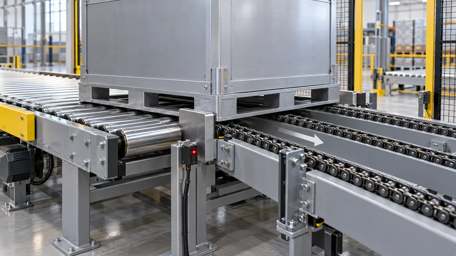
Design a conveyor steel pallet from the actual support, transfer and control geometry supplied by the conveyor integrator. Continuous runners must stay supported across roller pitch and transfer gaps, while chain-track centres must align with the pallet's intended contact lines. A roller-to-chain or 90-degree transfer also needs clear underside space for the lifting mechanism, a repeatable stop face and an unobstructed sensor target. Review raised and lowered equipment states plus loaded, empty and slightly skewed pallet positions before fixing the base drawing.
Industry equipment pages make the interface visible. Broich Systemtechnik shows heavy-duty roller systems with front or side loading, chain transfers and sensor options. Interroll's chain-transfer module documentation identifies chain count, spacing and stop positions as equipment-specific inputs. These are not HAOFU specifications. They illustrate why “conveyor compatible” is not enough information for a custom steel pallet quotation.
Use one interface drawing for pallet and conveyor suppliers
The drawing should overlay the loaded pallet underside with every conveyor contact. Mark roller axes and pitch, chain centre lines and widths, guide rails, the transfer gap, lift stroke, stop position and sensor sightline. Add the pallet's load-bearing runners, cross-members, feet, fork openings, stacking features and intended travel direction. Conflicts become visible before steel is cut: a fork pocket crossing a chain track, a weld joint landing on a roller gap or a foot entering the lift-table space.
| Equipment feature | What it asks of the pallet | Drawing or data to request | Buyer decision |
|---|---|---|---|
| Powered rollers | Continuous, straight contact lines that bridge the actual pitch and transfer gaps. | Roller diameter, pitch, usable width, axes, gaps and travel direction. | Runner direction, length, flatness reference and prohibited underside features. |
| Two- or three-strand chains | Runner centre lines that land on each chain through the transfer tolerance. | Chain centres, track width, elevation and guide arrangement. | Number and spacing of runners plus load path into the pallet deck. |
| Pop-up or 90° transfer | Open clear zones for lifting chains or rollers and support in both directions. | Raised/lowered section views, stroke, entry direction and transfer sequence. | Cross-member positions, underside clearance and bidirectional support. |
| Mechanical stop | A durable, repeatable face that can be reached without contacting a foot or loose feature. | Stop location, height, direction and operating sequence. | Stop plate geometry and load path into the base frame. |
| Photoelectric/proximity sensor | A consistent target or clear detection window unaffected by holes, labels or cargo overhang. | Sensor type, beam/field position, bracket and required target zone. | Detection flag, target face and keep-clear area. |
Continuous runners bridge roller pitch and transfer gaps while keeping welds, feet and fork features out of the rolling path.
Runner centres must match the actual chain tracks, and cross-members must clear any lift or cross-transfer mechanism.
Review raised and lowered states, support in both directions, a repeatable stop face and a visible sensor target.
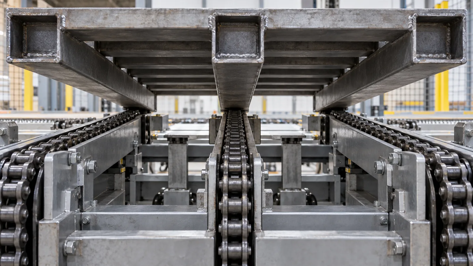
Runner continuity matters on rollers
A roller conveyor supports the pallet at successive narrow lines. A continuous runner spreads that changing support into the pallet base, but its length, straightness and orientation must suit the real equipment. Check where the runner enters the first roller, crosses between conveyor modules and leaves the last one. Feet, weld beads, drain features or fork-pocket edges should not create an unintended step in the rolling path.
This differs from the general deck-surface choice covered in the steel pallet deck guide. The deck supports the cargo; the runner interface transfers the complete unit load into the conveyor. It also differs from forklift handoff, although both interfaces must coexist in the final pallet base.
Match chain tracks and clear the lift mechanism
On a chain conveyor, the load-bearing strips need to align with the actual tracks. Do not assume that a nominal pallet width determines those centres. A three-strand layout can require a centre runner; a two-strand layout may put support closer to the outer frame. The pallet structure must carry cargo loads into those lines without relying on an unplanned sheet edge or cross-member.
At a 90-degree transfer, a secondary mechanism rises through or between the first conveyor's support lines. Ask for section views in both lowered and raised states. Show the transfer sequence, not only the final elevations. The pallet must remain supported while one mechanism hands it to the other, and underside members must stay outside the moving equipment envelope.
Give stops and sensors deliberate pallet features
A conveyor stop should meet a defined base-frame face rather than a caster-like foot, diagonal edge or cargo overhang. Draw the stop direction and contact height so the resulting force enters the pallet structure. Separately, reserve a clean target for detection. Holes, reflective wrap, varying loads or labels can make an improvised target inconsistent; the integrator should state the detection technology and target requirement.
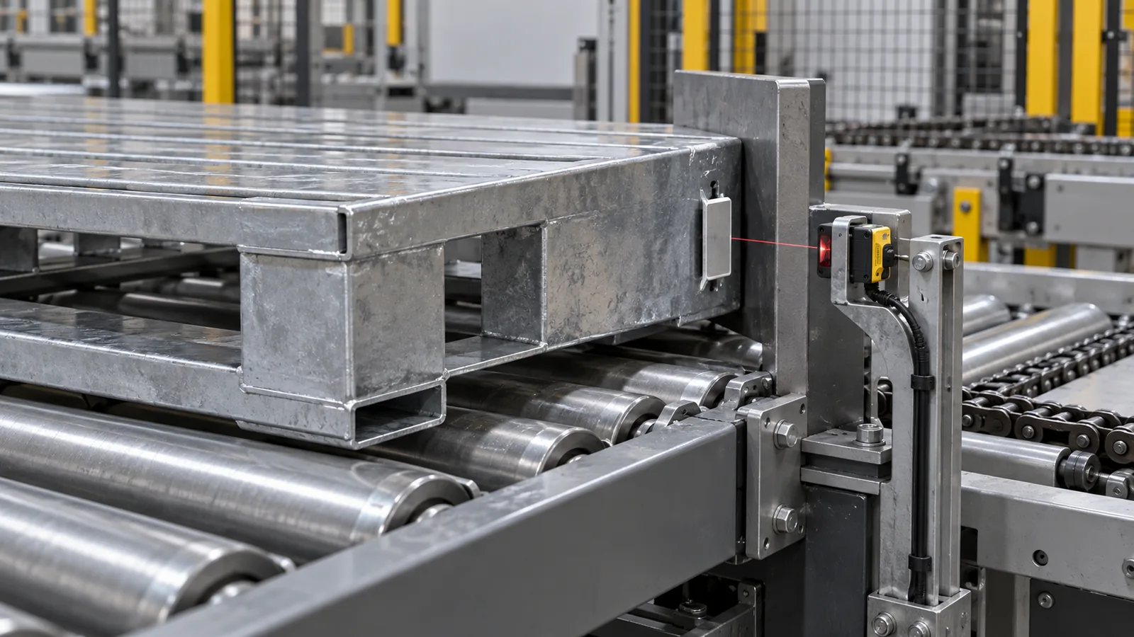
Check loaded, empty and skewed states
An empty steel pallet may behave differently because its traction, inertia and centre of gravity have changed. A loaded pallet may deflect or present cargo overhang near guides and sensors. Include both conditions in the trial plan. Also review the placement tolerance and a credible skewed entry: runners still need to find the support path, side guides must engage an appropriate face and the stop should not twist the pallet into a jam.
ASME B20.1-2024 covers conveyor-related hazards across design, installation, maintenance, inspection and operation. Referencing it here does not claim pallet or conveyor compliance. The conveyor integrator and site safety owner remain responsible for the applicable design and guarding decisions.
- Obtain the conveyor interface drawingCollect roller, chain, guide, stop, sensor and lift geometry from the integrator.
- Map every support stateShow contact lines before, during and after the transfer in both travel directions.
- Design the pallet undersideAlign runners, cross-members and clear zones with the actual equipment.
- Add repeatable control facesProvide deliberate guide, stop and detection surfaces that remain visible and accessible.
- Trial loaded and empty transfersCheck entry, stopping, lifting, 90-degree exit and recovery with production-intent hardware.
Five steps to specify the transfer interface
- Obtain the conveyor interface drawing. Collect roller, chain, guide, stop, sensor and lift geometry from the equipment integrator.
- Map every support state. Show contact lines before, during and after the transfer, including raised and lowered mechanisms.
- Design the pallet underside. Align runners and load paths while reserving clear zones for moving equipment, fork entry and stacking features.
- Add repeatable control faces. Define guide surfaces, a structural stop face and a stable detection target.
- Trial loaded and empty transfers. Check straight and skewed entry, stopping, lifting, 90-degree exit and recovery with production-intent hardware.
What to send for a custom steel pallet quotation
Send the unit-load bottom view, mass and centre-of-gravity information, support points and restraint needs; pallet envelope and travel orientation; roller diameter, pitch, axes and transfer gaps; chain count, width, centres and elevations; raised/lowered transfer sections; guides, stops and sensors; fork or pallet-truck access; floor and storage conditions; loaded and empty states; quantity, destination and trial requirement. Review custom steel pallets, then send the load and conveyor interface drawings for an engineering quotation.
Frequently Asked Questions
- What makes a steel pallet compatible with a roller conveyor?
- Its continuous underside runners must stay supported across the actual roller pitch and transfer gaps, while joints, feet, fork features and welds remain out of the rolling path.
- How should pallet runners align with a chain conveyor?
- Runner centre lines and usable widths should match the conveyor's actual chain tracks through the permitted placement tolerance. The pallet load path must transfer the unit load into those runners.
- What changes at a roller-to-chain or 90-degree transfer?
- A lifting or cross-transfer mechanism enters the pallet underside, so raised and lowered equipment states, clearance, support in both directions and the full transfer sequence must be reviewed.
- Does a conveyor pallet need a dedicated stop face?
- A deliberate structural stop face gives the equipment a repeatable contact instead of striking a foot, diagonal edge or cargo overhang. Its height and load path should be agreed with the integrator.
- Why add a dedicated sensor target to a steel pallet?
- A stable target or detection window reduces ambiguity from holes, varying cargo, labels or reflective wrapping. The conveyor integrator should specify the sensor technology and target requirement.
- What should I send for a conveyor steel pallet quotation?
- Send the unit-load bottom view, mass and centre of gravity, pallet envelope, roller and chain geometry, transfer sections, guides, stops, sensors, fork access, loaded and empty states, quantity, destination and trial requirement.