
Custom Automotive Connecting Rod Rack with Pneumatic Trays
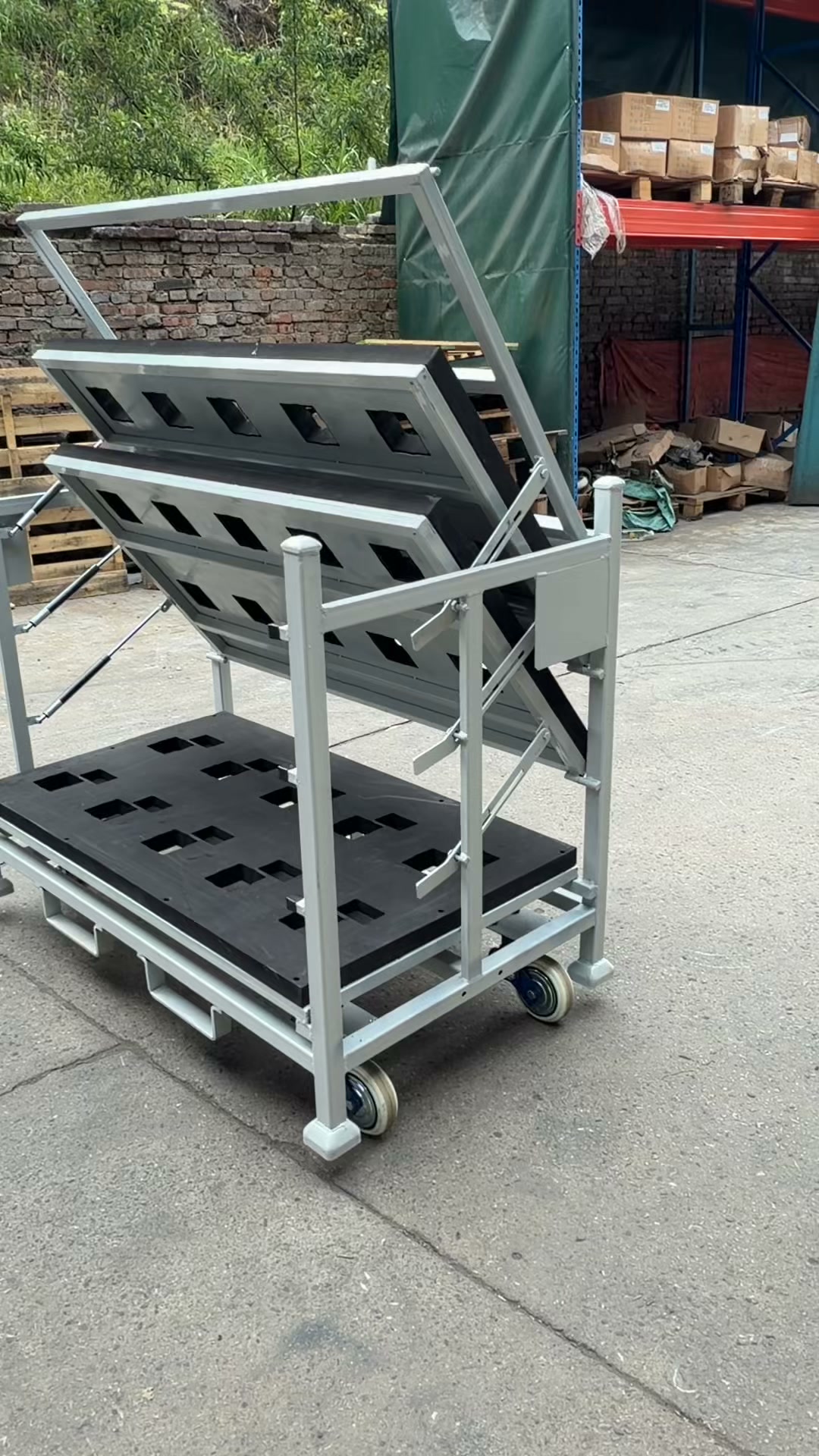
See custom automotive connecting rod rack with pneumatic trays in an automotive-parts logistics application. The video highlights casters, pneumatic assistance. It gives packaging engineers and procurement teams a product-level view of the rack arrangement shown for the stated component or application. Look at the frame, part-contact areas, loading access, base and moving features that are actually visible, then compare them with your own part size, weight, orientation and protection needs. The related product category is Automotive Parts Racks. For a custom quotation, send the part drawing or photos, quantity per rack, loading method, forklift or line-side conditions, stacking and empty-return needs, project quantity and destination.
By HAOFU Engineering Team · Updated 2026-08-10
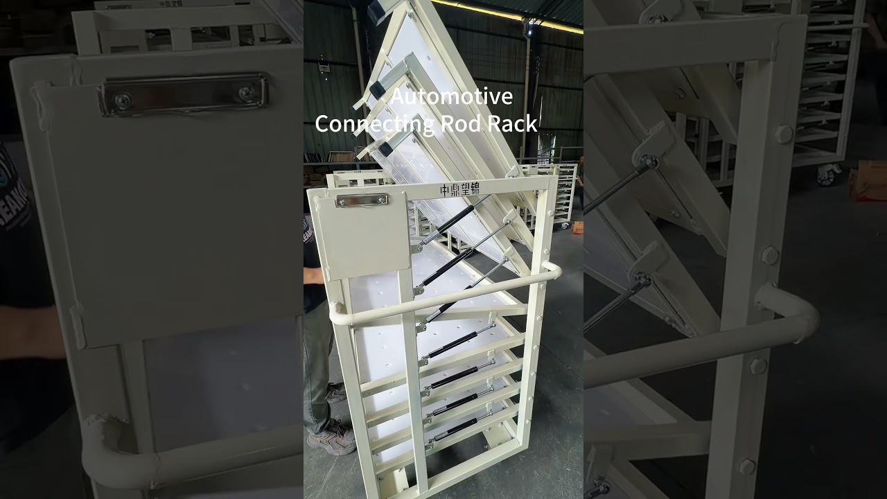
- Video focus: Custom Automotive Connecting Rod Rack with Pneumatic Trays.
- Recorded details: Casters, Pneumatic assistance.
- Closest product path: Automotive Parts Racks.
- Buyer decision: confirm part fit, access, handling and return conditions for the actual project.
- Next step: send drawings and route requirements through HAOFU customization.
Direct answer
What is shown in this video?
Custom Automotive Connecting Rod Rack with Pneumatic Trays shows a HAOFU product showcase example for automotive parts logistics. Visible details include casters, pneumatic assistance. Use it to compare frame, part support, loading access and handling ideas. For a similar Automotive Parts Racks project, provide the part drawing, quantity per rack, loading method, handling route, stacking, empty return and destination.
What the Video Shows
The footage focuses on custom automotive connecting rod rack with pneumatic trays. Useful details include the visible structure, contact arrangement, access method or manufacturing stage and how those choices support the application shown.
- MobilityCasters
- Opening supportPneumatic assistance
Use the product catalog to compare the broader category. For a project matched to your component geometry and logistics route, continue to customization with drawings and handling requirements.
Related Products
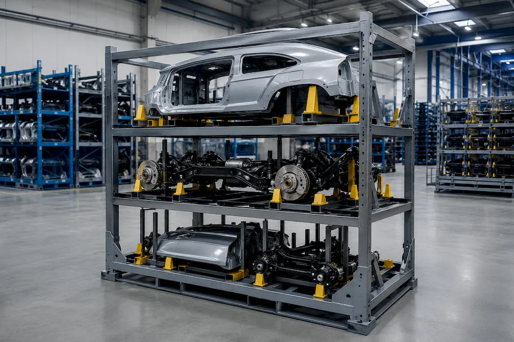
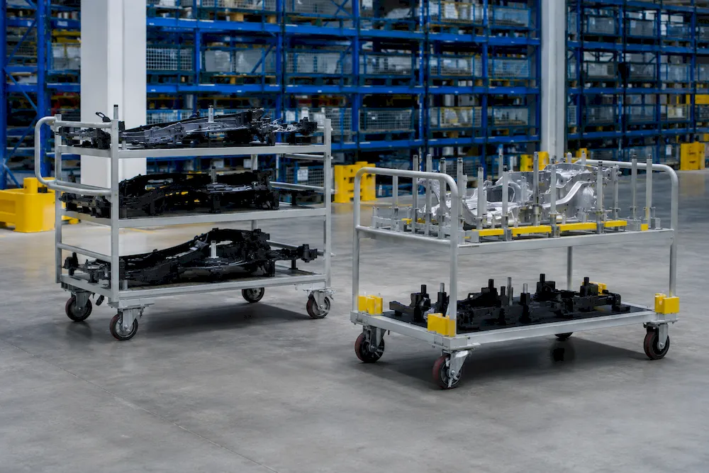
These are the closest real HAOFU product routes and provide a practical category starting point before project customization.
Details Shown in This Video
Use these visible details to compare configurations. Dimensions, ratings, materials, finishes and commercial terms for a new project are set from your part data and quotation requirements.
| Field | Visible detail | Source |
|---|---|---|
| Mobility | Casters | Video-specific data |
| Opening support | Pneumatic assistance | Video-specific data |
| Video category | Automotive Parts Racks | Video-specific data |
| Video type | product showcase | Video-specific data |
Custom Automotive Connecting Rod Rack with Pneumatic Trays: video configuration and RFQ choices
| Design area | Visible in this video | Information for your project |
|---|---|---|
| Part interface | Mobility: Casters | Contact map based on the actual part |
| Access and loading | Opening support: Pneumatic assistance | Manual, forklift, tugger, AGV or line-side method |
| Protection method | Part separation as shown | Dunnage selected for surface and route |
| Return and storage | Current project configuration | Stacking, nesting, folding or fixed-frame requirement |
Custom Automotive Connecting Rod Rack with Pneumatic Trays: custom rack development flow
- 1
Send part data
Provide drawings, photos, surfaces and quantity per rack.
- 2
Map the route
Define loading, handling, storage, stacking and return conditions.
- 3
Review concept
Check the frame, contact points, access and equipment interfaces.
- 4
Confirm the design
Review the proposed rack, sample checks and production requirements.
Project inputs
Customization: What We Need From You
- ✓Part drawing, sample photos and protected contact surfaces
- ✓Quantity and orientation required in each rack
- ✓Loading direction, operator access and handling equipment
- ✓Stacking, storage and empty-return requirements
- ✓Destination, project quantity and inspection requirements
Frequently Asked Questions
What does the Custom Automotive Connecting Rod Rack with Pneumatic Trays video show?
It shows mobility: Casters; opening support: Pneumatic assistance. Use the example to identify useful features, then specify a new rack from your own part and route requirements.
Which HAOFU product is most closely related to this video?
The closest catalog route is Automotive Parts Racks. Use that product page to understand the category, then submit project data for a configuration matched to the actual part and route.
Are the video details standard specifications for every project?
The details shown describe this example. Dimensions, capacity, materials, interfaces and finish for a new project are selected from the actual part, handling route and quotation requirements.
What information should a buyer send for a related project?
Start with part drawing, sample photos and protected contact surfaces, quantity and orientation required in each rack, loading direction, operator access and handling equipment, stacking, storage and empty-return requirements. These inputs let the engineering discussion focus on part fit and the real handling route.
How can I request a quotation for a similar rack?
Use the customization form to send drawings, photos, quantity per rack, handling conditions, project volume and destination. HAOFU can then review the application and respond around the supplied requirements.
Related Videos & Guides
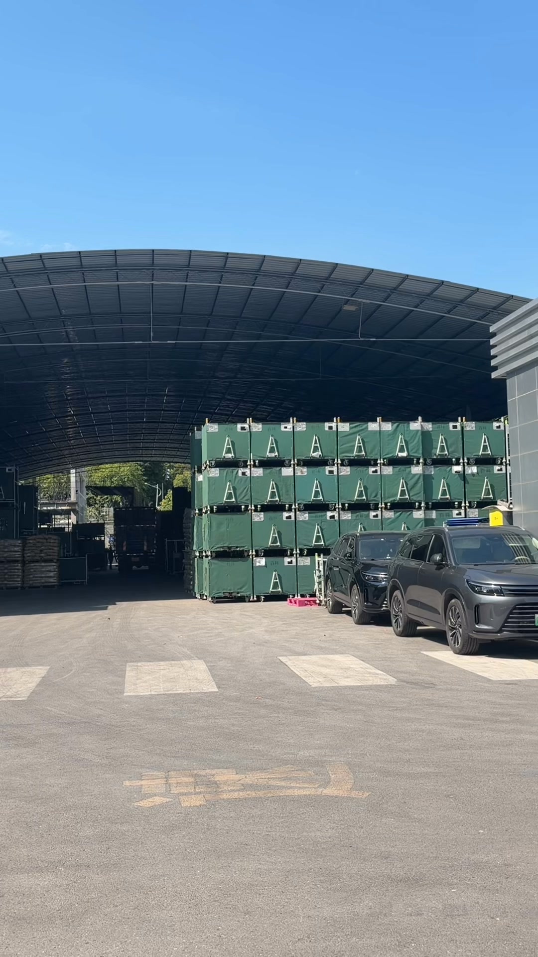
Automotive Parts Racks in Service — After-Sales Site Visit
Brake Master Cylinder Rack — 3-Tier, 30 Parts, CNC-Cut EVA
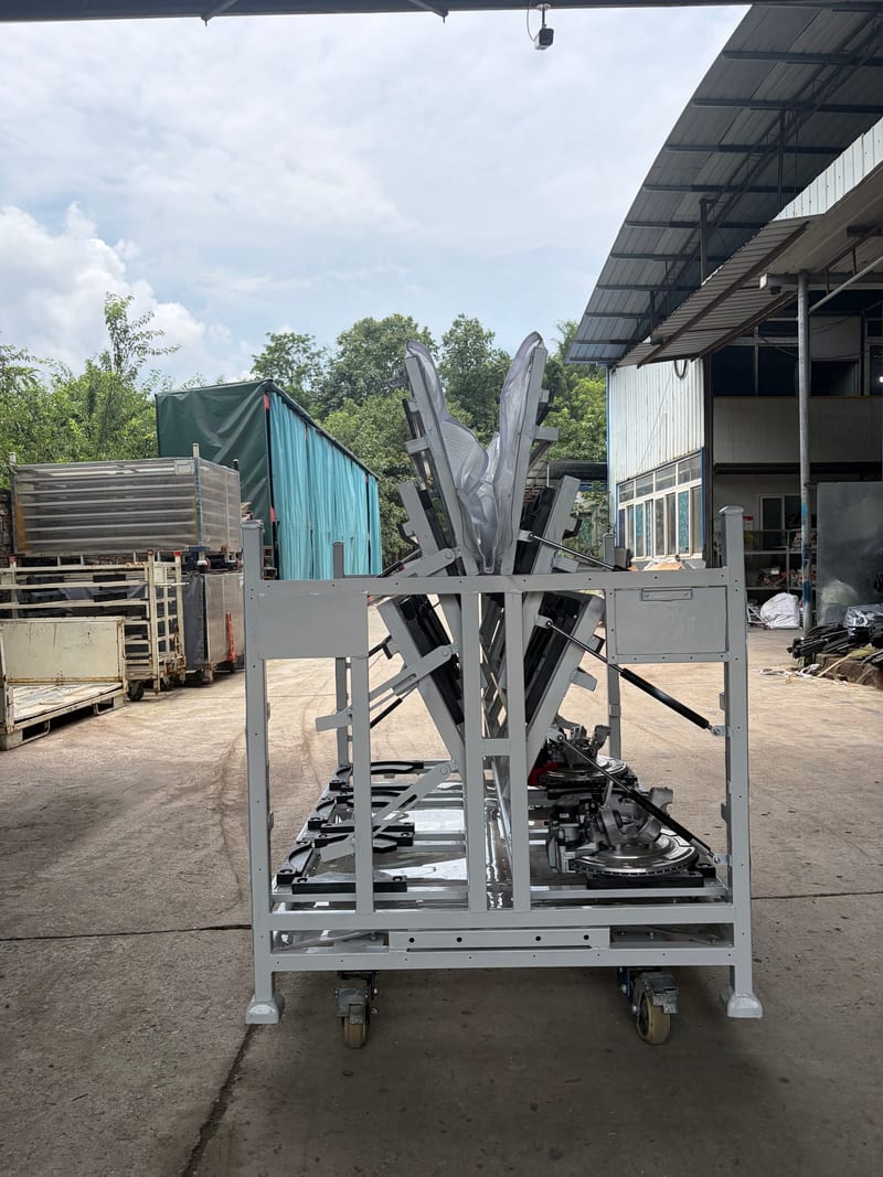
Catalytic Converter Rack — Hydraulic Supports, Robotic Arms & EVA Inserts
Inside Our Metal Rack Factory — Designed, Welded, Finished, Inspected
Custom rack project
Specify a custom automotive connecting rod rack with pneumatic trays for your parts
Share the part drawing, quantity per rack, loading method, handling route, project volume and destination. The response will be based on the supplied project requirements.
Send Drawings & Requirements →